Liquid crystal display panel and liquid crystal display device

A technology of liquid crystal display panel and display area

Active Publication Date: 2016-01-06
SHENZHEN CHINA STAR OPTOELECTRONICS TECH CO LTD
View PDF4 Cites 12 Cited by
  • Summary
  • Abstract
  • Description
  • Claims
  • Application Information

AI Technical Summary

Problems solved by technology

like Figure 9A , Figure 9B and Figure 9C As shown, in the existing color filter substrate, a protruding retaining wall member 12' is arranged at the edge thereof, and when the PI liquid 30' flows through the retaining wall member 12' along the A' direction, it will receive a relatively large r

Method used


Image

  • Liquid crystal display panel and liquid crystal display device
  • Liquid crystal display panel and liquid crystal display device
  • Liquid crystal display panel and liquid crystal display device

Examples


Embodiment Construction

[0030] The present invention will be further described below in conjunction with the drawings.

[0031] The details introduced here are exemplary and are only used to exemplify the discussion of the embodiments of the present invention. Their existence is to provide what is considered to be the most useful and understandable description of the principles and concepts of the present invention. Regarding this point, there is no attempt to introduce the structural details of the present invention beyond the level required for a basic understanding of the present invention. Those skilled in the art can clearly understand how to implement the present invention in practice through the description and drawings. Several forms.

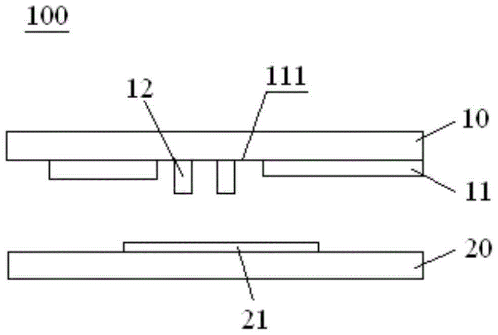
[0032] figure 1 The schematic diagram of the structure of the liquid crystal display panel 100 provided according to the present invention is shown. The liquid crystal display panel 100 includes a color filter substrate 10, and the color filter substrate 10 inclu...


PUM


Abstract

The invention discloses a liquid crystal display panel and a liquid crystal display device. The liquid crystal display panel comprises a color film substrate. The color film substrate comprises a display area. The edge of the display area comprises a black matrix layer provided with a groove. Barrier wall components are arranged in the groove, and the height of the barrier wall components is larger than the thickness of the black matrix layer. The liquid crystal display panel can achieve image display with higher quality, and meanwhile narrow bezel design of the liquid crystal display panel can be achieved more easily.

Description

Technical field [0001] The invention belongs to the technical field of liquid crystal display, and specifically relates to a liquid crystal display panel and a liquid crystal display device. Background technique [0002] In the field of TFT-LCD (ThinFilmTransistorLiquidCrystalDisplay), a PI layer is usually coated on the color film substrate and the array substrate to form a pretilt angle. The PI layer is used to make the liquid crystal have a fixed inverting direction, which is beneficial to the liquid crystal display. [0003] However, since the sealant is usually applied to the edge of the color filter substrate, and the conversion layer is also close to the sealant, the coating of the PI layer on the edge of the color filter substrate cannot exceed the position of the sealant, that is, the edge of the PI layer must Between the display area and the inner edge of the sealant, otherwise the sealant will fall off, causing the LCD panel to display abnormally. In the prior art, barr...

Claims


Application Information

Patent Timeline
IPC IPC(8): G02F1/1339G02F1/1335
CPCG02F1/133512G02F1/1337G02F1/13394
Inventor 黄世帅
Owner SHENZHEN CHINA STAR OPTOELECTRONICS TECH CO LTD
Why Eureka
Try Eureka