
Non-contact absolute position knob

A non-contact, absolute position technology, applied in the direction of electrical components, pulse technology, electronic switches, etc., can solve the problems of pollutants entering the outside of the equipment, weakening the force strength of the panel, and hindering the cleaning of the panel, so as to avoid pollution and damage , The structure is simple and novel, and the effect of ensuring integrity

Inactive Publication Date: 2016-01-06
NINGBO FOTILE KITCHEN WARE CO LTD
View PDF7 Cites 9 Cited by
  • Summary
  • Abstract
  • Description
  • Claims
  • Application Information

AI Technical Summary

Problems solved by technology

[0002] Most of the existing switch knobs are physically connected switch knobs, such as potentiometer-type switch knobs and bar-coded switch knobs. This kind of physically connected knobs will not only affect the service life due to the wear and tear of the mechanical structure during use, but also physically connect When the knob is used, it is necessary to open holes on the panel of the electrical equipment, destroying the integrity and sealing of the equipment shell, resulting in a greatly weakened panel's stress strength, and also causing pollutants outside the equipment to enter the interior of the equipment, which is harmful to the equipment. The internal parts and circuits constitute pollution and damage, and also hinder the cleaning of the panel to a certain extent

Method used


Image

  • Non-contact absolute position knob
  • Non-contact absolute position knob
  • Non-contact absolute position knob

Examples


Embodiment Construction

[0016] The present invention will be further described in detail below in conjunction with the accompanying drawings and embodiments.

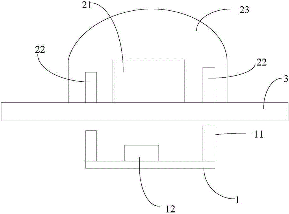
[0017] Such as figure 1 The shown non-contact absolute position knob includes an induction switch circuit board and an induction knob, and the induction switch circuit board and the induction knob are respectively placed on both sides of the operation panel 3, wherein

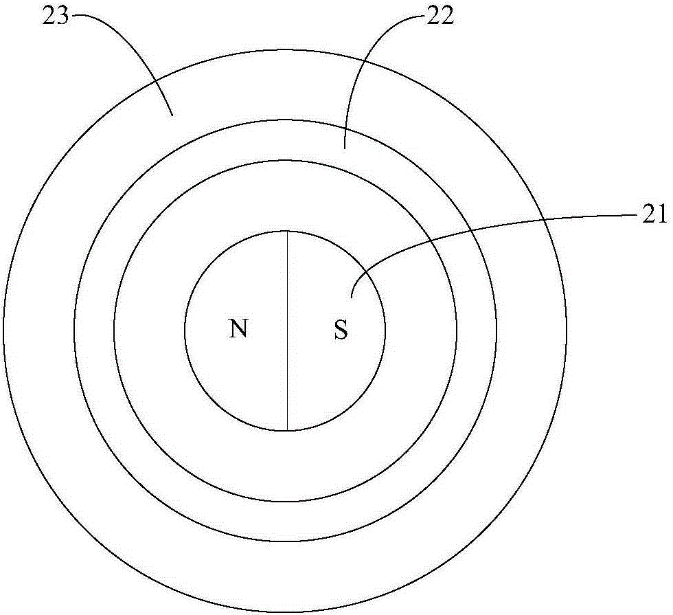
[0018] The induction knob includes a cylindrical shape located at the center and an induction permanent magnet 21 with N poles and S poles on the same plane, and the center of the N poles and S poles is symmetrical, and the first circular positioning permanent magnet 22 arranged outside the induction permanent magnet , and the rotatable knob base 23 for fixing the induction permanent magnet and the first annular positioning permanent magnet, see figure 2 shown;

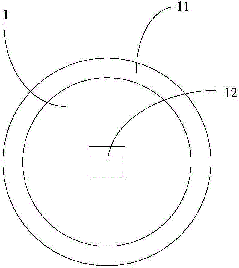
[0019] The induction switch circuit board 1 is provided with a second annular positioning permanent magnet 11, a ...


PUM


Abstract

The invention relates to a non-contact absolute position knob, which comprises an inductive switch circuit board and an inductive knob, wherein the inductive switch circuit board and the inductive knob are respectively placed at two sides of an operation panel. The non-contact absolute position knob is characterized in that the inductive knob comprises an inductive permanent magnet, a first annular locating permanent magnet and a rotary knob base, wherein an N pole and an S pole of the inductive permanent magnet are arranged on one cylindrical surface at a central position and are centrally symmetrical; the first annular locating permanent magnet is arranged outside the inductive permanent magnet; the rotary knob base is used for fixing the inductive permanent magnet and the first annular locating permanent magnet; a second annular locating permanent magnet, a magnetic induction element capable of detecting rotation of the inductive permanent magnet to generate magnetic variation and an MCU (Micro Control Unit) unit connected to the magnetic induction element and used for computing a rotation angle of the inductive knob are arranged on the inductive switch circuit board. The non-contact absolute position knob has the advantages of novel structure, linear rotation angle position detection and no need to open a hole on electrical equipment.

Description

technical field [0001] The invention relates to a switch knob, in particular to a non-contact absolute position knob. Background technique [0002] Most of the existing switch knobs are physically connected switch knobs, such as potentiometer-type switch knobs and bar-coded switch knobs. This kind of physically connected knobs will not only affect the service life due to the wear and tear of the mechanical structure during use, but also physically connect When the knob is used, it is necessary to open holes on the panel of the electrical equipment, destroying the integrity and sealing of the equipment shell, resulting in a greatly weakened panel's stress strength, and also causing pollutants outside the equipment to enter the interior of the equipment, which is harmful to the equipment. The internal parts and circuits constitute pollution and damage, and also hinder the cleaning of the panel to a certain extent. [0003] For this reason, people have proposed a kind of induc...

Claims


Application Information

Patent Timeline
Patent Type & Authority Applications(China)
IPC IPC(8): H03K17/95
Inventor 史井雄谭蓁曾令均严力峰茅忠群诸永定方献良
Owner NINGBO FOTILE KITCHEN WARE CO LTD
Learn More