
Gas density measuring device

A measuring device and gas density technology, applied in the direction of measuring device, specific gravity measurement, special recording/indicating device, etc., can solve problems affecting safe and stable operation, false alarm of density relay, long GIS interval, etc., to achieve reasonable distribution of measuring points, Reduce measurement error and achieve good linearity

Active Publication Date: 2018-11-13
ELECTRIC POWER RESEARCH INSTITUTE, CHINA SOUTHERN POWER GRID CO LTD +1
View PDF7 Cites 0 Cited by
  • Summary
  • Abstract
  • Description
  • Claims
  • Application Information

AI Technical Summary

Problems solved by technology

However, this type of density relay has many shortcomings in practical applications: the spring tube, as a nonlinear element, only shows an approximately linear relationship with the gas pressure measured in the tube within a specific pressure range, and there is still a certain error; It can only compensate the temperature value of its location, while the interval of GIS is long. When there is a temperature gradient inside the GIS gas chamber due to factors such as direct sunlight and sudden temperature changes, the bimetal sheet cannot correctly compensate the actual temperature. , causing measurement errors, and then causing the density relay to issue false alarms or false blocking signals, seriously affecting the safe and stable operation of GIS

Method used


Image

  • Gas density measuring device
  • Gas density measuring device
  • Gas density measuring device

Examples


Embodiment Construction

[0026] The following will clearly and completely describe the technical solutions in the embodiments of the present invention with reference to the accompanying drawings in the embodiments of the present invention. Obviously, the described embodiments are only some, not all, embodiments of the present invention. Based on the embodiments of the present invention, all other embodiments obtained by persons of ordinary skill in the art without creative efforts fall within the protection scope of the present invention.

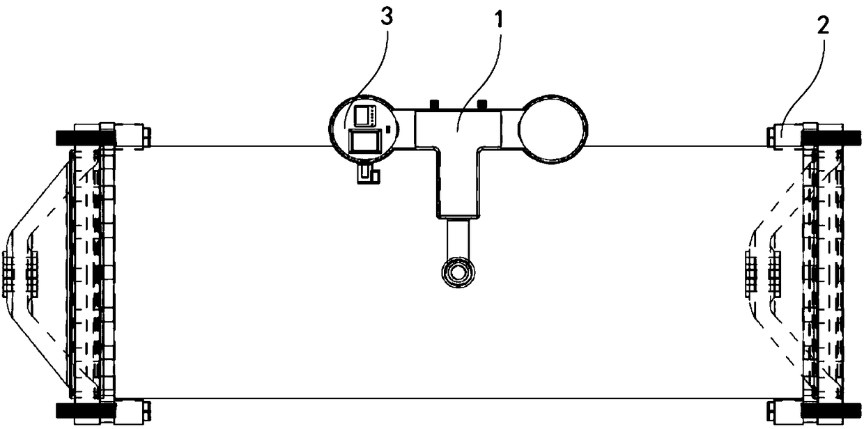
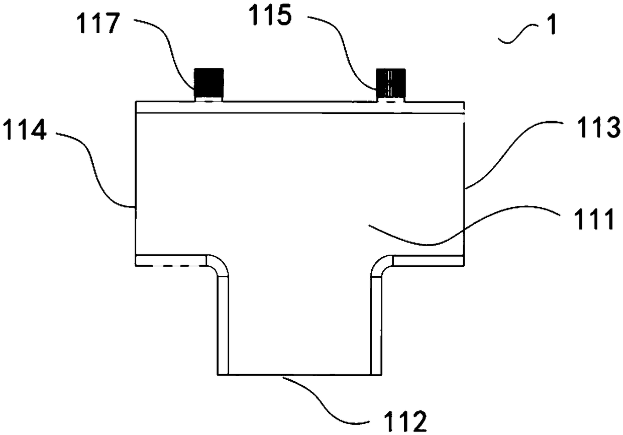
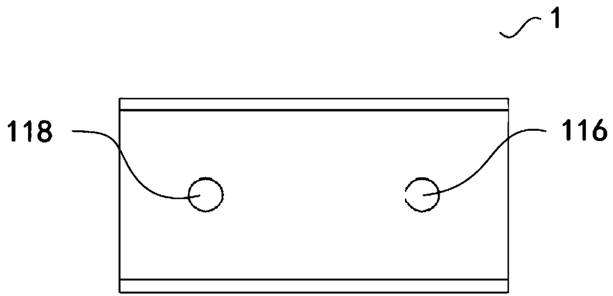
[0027] see Figure 1 to Figure 7 ,in, figure 1 It is the overall assembly drawing of the gas density measuring device provided by the embodiment of the present invention; figure 2 yes figure 1 The structural front view of the three-way control valve described in; image 3 yes figure 1 The bottom view of the structure of the three-way control valve described in; Figure 4 yes figure 1 The structural side view of the three-way control valve described in; Fig...


PUM


Abstract

The invention provides a gas density measuring device. The gas density measuring device comprises a three-way control valve, wherein the three-way control valve comprises a three-way control valve body provided with an air inlet interface connected with a GIS density relay and a first air outlet interface and a second air outlet interface which are communicated with a mechanical density relay; a plurality of temperature detectors disposed inside a flange of a GIS casing, wherein each temperature detector includes a surface acoustic wave temperature sensor for detecting temperature data of theposition where the temperature detector is located; a processing assembly, wherein the processing assembly comprises a processing assembly casing, a temperature collector disposed inside the processing assembly casing and a pressure sensor for detecting pressure data at the position. The temperature collector is wirelessly connected to the surface acoustic wave temperature sensors. The processingassembly casing is provided with a pneumatic circuit interface connected to the second air outlet interface and a bus outlet electrically connected to a control cubicle. The device can reduce the measurement error caused by temperature change and has good linearity and high measurement accuracy.

Description

technical field [0001] The invention relates to the technical field of gas density measurement, in particular to a gas density measurement device. Background technique [0002] Gas insulated closed combined electrical appliances (English: GAS Insulated SWITCHGEAR, referred to as: GIS) are filled with a certain pressure of SF 6 As an insulating medium, gas has excellent insulating properties. When the internal pressure of GIS deviates from the rated value, the density relay can reflect the current pressure value of the air chamber in time, and output an alarm or blocking signal. [0003] At present, the commonly used density relay uses the spring tube as the measuring element, uses the built-in bimetal of the instrument to perform temperature compensation on the measured air pressure, and then converts it to obtain the current SF inside the air chamber at 20°C 6 Gas pressure value. However, this type of density relay has many shortcomings in practical applications: the spr...

Claims


Application Information

Patent Timeline
Patent Type & Authority Applications(China)
IPC IPC(8): G01N9/26G01D3/036
CPCG01D3/036G01N9/266
Inventor 黄若栋高超周福升杨芸王国利陈曦喇元
Owner ELECTRIC POWER RESEARCH INSTITUTE, CHINA SOUTHERN POWER GRID CO LTD
Learn More