Riveting pin clamp for lock tongue cover plate
A cover plate and riveting pin technology, which is applied in the field of assembly aids for automobile switches, can solve problems such as time-consuming and labor-intensive fixtures, and achieve the effects of improving riveting efficiency, avoiding operation accidents, and improving riveting quality
- Summary
- Abstract
- Description
- Claims
- Application Information
AI Technical Summary
Problems solved by technology
Method used
Image

Examples
Embodiment
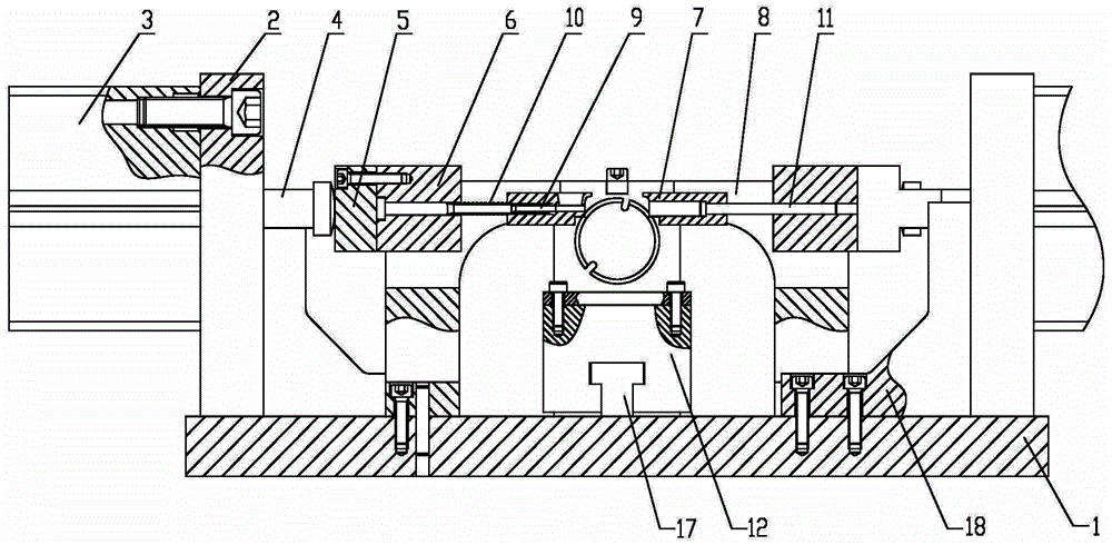
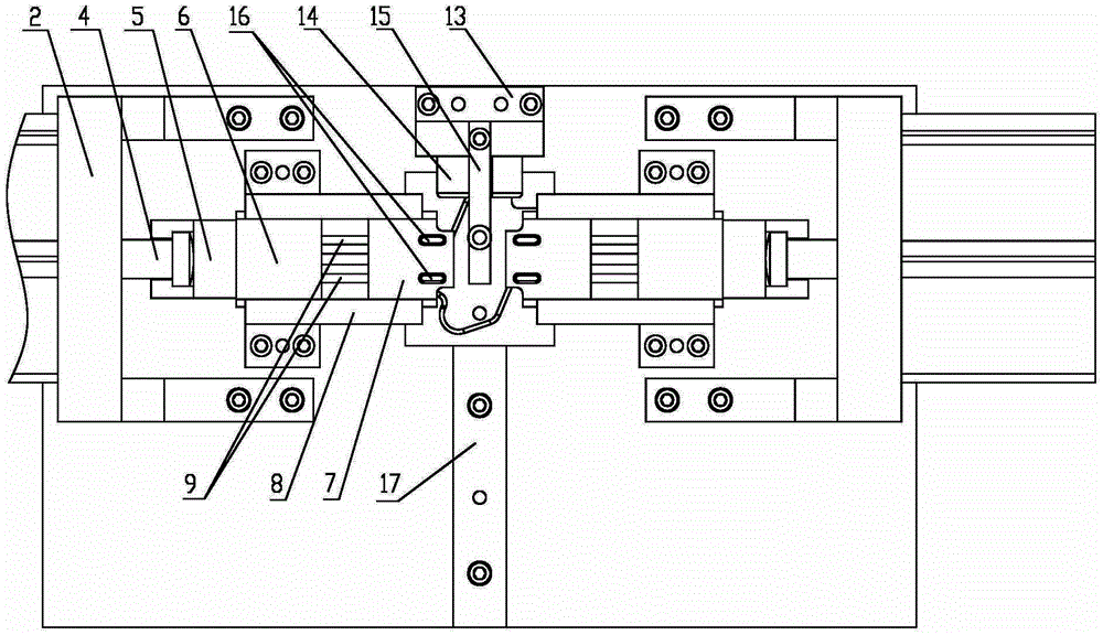
[0021] Please also refer to Figures 2 to 3 , a riveting fixture for a deadbolt cover plate, comprising a bottom plate 1, a cylinder fixing plate 2, a cylinder 3, a cylinder connecting shaft 4, a floating joint 5, a punch fixing block 6 and a preloading block 7.
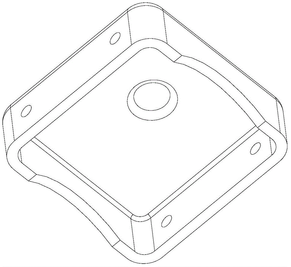
[0022] Wherein, the central position of base plate 1 is provided with positioning block 12, and positioning block 12 is provided with the mold cavity that is used for placing deadbolt cover plate, is also provided with guide plate 17 between positioning block 12 and base plate 1, and positioning block 12 bottom is provided with The groove matched with the guide plate 17, the above-mentioned positioning block 12 can move on the guide plate 17. On the base plate 1, a vertical plate 13 is fixed near the rear side of the positioning block 12, and the vertical plate 13 is provided with a hole, and a positioning shaft 14 is installed in the hole, and the top of the vertical plate 13 is also fixed with a pressing plate 15. ...
PUM
 Abstract
Description
Claims
Application Information
PatSnap Eureka turns technology decisions into work you can execute. Powered by our Innovation Knowledge Graph, it runs expert workflows across engineering, life sciences, materials and intellectual property. Get your review-ready output in minutes.


