Resistance strain gauge

A resistance strain gauge, longitudinal technology, applied in the direction of electric/magnetic solid deformation measurement, electromagnetic measuring device, measuring device, etc., can solve problems such as errors, difficult positioning, difficulty in observing the pasting coordinates of strain gauges, etc., to achieve convenient pasting, reduce small area effect

Inactive Publication Date: 2016-01-13
SHANGHAI INST OF TECH
View PDF6 Cites 11 Cited by
  • Summary
  • Abstract
  • Description
  • Claims
  • Application Information

AI Technical Summary

Problems solved by technology

[0004] Similarly, under the action of a bending force P with a certain offset from the axis, the traditional right-angle strain gauges can overcome the asymmetrical influence of the bending force even if they are arranged in parallel by 90 degrees because the strain gauges in two directions are arranged in parallel, but Under the action of the offset distance of P force, the center of the vertical sensitive grid and the center of the horizontal sensitive grid and the patch X 2 There is an offset distance e from the axis 1 , so under the action of P force, the longitudinal and transverse strain values ​​will be different, no matter what kind of measurement circuit, the measured strain value has a certain error with the actual strain value
[0005] In addition, due to the small area of ​​the resistance strain gauge itself, under some unsatisfactory lighting conditions, the sticking coordinates of the strain gauge are often difficult to observe, which brings great difficulties to the precise positioning during the sticking process

Method used


Image

  • Resistance strain gauge
  • Resistance strain gauge

Examples


Embodiment Construction

[0017] The present invention will be further described below in conjunction with the accompanying drawings and embodiments.

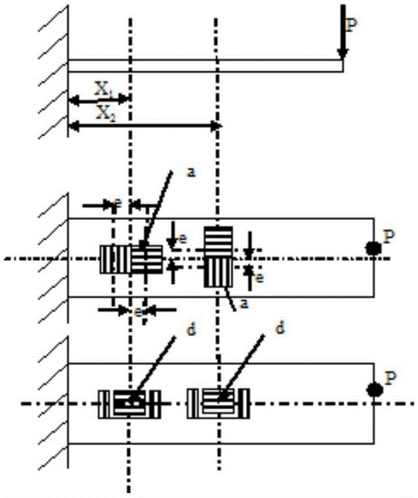
[0018] Such as figure 2 As shown, a new type of resistance strain gauge consists of two units of vertical sensitive grid 1, horizontal sensitive grid 2, shorting wire 3, and longitudinal coordinate 4 and horizontal coordinate 5 with reflective performance.

[0019] The vertical sensitive grid 1 and the horizontal sensitive grid 2 are structurally symmetrical on the longitudinal coordinate 4 and the transverse coordinate 5, which are used to eliminate measurement errors under the action of non-simple loads. The longitudinal sensitive grid 1 is divided into two units, and the two units are connected by a shorting wire 3, and the shorting wire 2 is connected to the strain gauge substrate without solidification, the shorting wire 3 does not participate in deformation, and the transverse sensitive grid 2 is embedded in the In the region of the vertical sen...


PUM


Abstract

The invention relates to a resistance strain gauge. A longitudinal sensitive grid and a horizontal sensitive grid are structurally symmetrical in longitudinal and transverse coordinates, and are used for eliminating measurement error under the effect of non-simple load. The longitudinal sensitive grid is divided into two units, and the two units are connected through a short circuit wire; the short circuit wire and a strain gauge substrate are in non-curing connection; the short circuit wire does not participate in deformation; and the horizontal sensitive grid is embedded in the longitudinal sensitive grid area without overlapping and causing interference, and convenient production is achieved. The longitudinal and transverse coordinates are coordinates having light-reflection performance, so that paste of the resistance strain gauge can be done conveniently under the condition of non-ideal illumination condition. Due to reasonable structural characteristics, the center of the longitudinal sensitive grid and the center of the horizontal sensitive grid are symmetrical with a paste center X1, so that longitudinal and horizontal strain values are same with actual strain values under the action of the bending force P; and the longitudinal and transverse coordinates both have light-reflection performance, so that the paste of the resistance strain gauge can be done conveniently under the condition of non-ideal illumination condition.

Description

technical field [0001] The invention relates to a resistance strain gauge, in particular to a form and arrangement of resistance versus strain gauges used in components with relatively complicated strain conditions. Background technique [0002] Resistance strain gauge is a commonly used stress and strain measuring element. It is firmly pasted on the measuring point of the component. After the component is stressed, the strain gauge is deformed due to the strain at the measuring point. The cross-sectional area also changes with the components, and then the resistance changes, and then the resistance change of the strain gauge is measured by a special instrument, and converted into the strain value of the measuring point. [0003] When the resistance strain gauge works, it is used to measure the real strain of the component by deforming together with the measured component. Due to the fact that the deformation of the component under the action of the load condition has a cer...

Claims


Application Information

Patent Timeline
Patent Type & Authority Applications(China)
IPC IPC(8): G01B7/16G01L1/22
Inventor 黄群石钢何卓仪吴伟金逸
Owner SHANGHAI INST OF TECH
Why Eureka
Try Eureka