Power steering device and method of controlling the power steering device

A power steering and control method technology, which is applied in the direction of automatic steering control components, steering mechanisms, steering rods, etc., can solve problems such as insufficient steering power and bad loads, and achieve the effect of smooth switching control and reduced manipulation physical strength

Inactive Publication Date: 2006-09-20
HITACHI LTD
View PDF1 Cites 19 Cited by
  • Summary
  • Abstract
  • Description
  • Claims
  • Application Information

AI Technical Summary

Problems solved by technology

[0009] However, in the aforementioned auxiliary steering assist method, during the rotation of the electric motor, the fluid flow resistance of the working fluid in the hydraulic circuit of th

Method used


Image

  • Power steering device and method of controlling the power steering device
  • Power steering device and method of controlling the power steering device
  • Power steering device and method of controlling the power steering device

Examples


no. 1 example

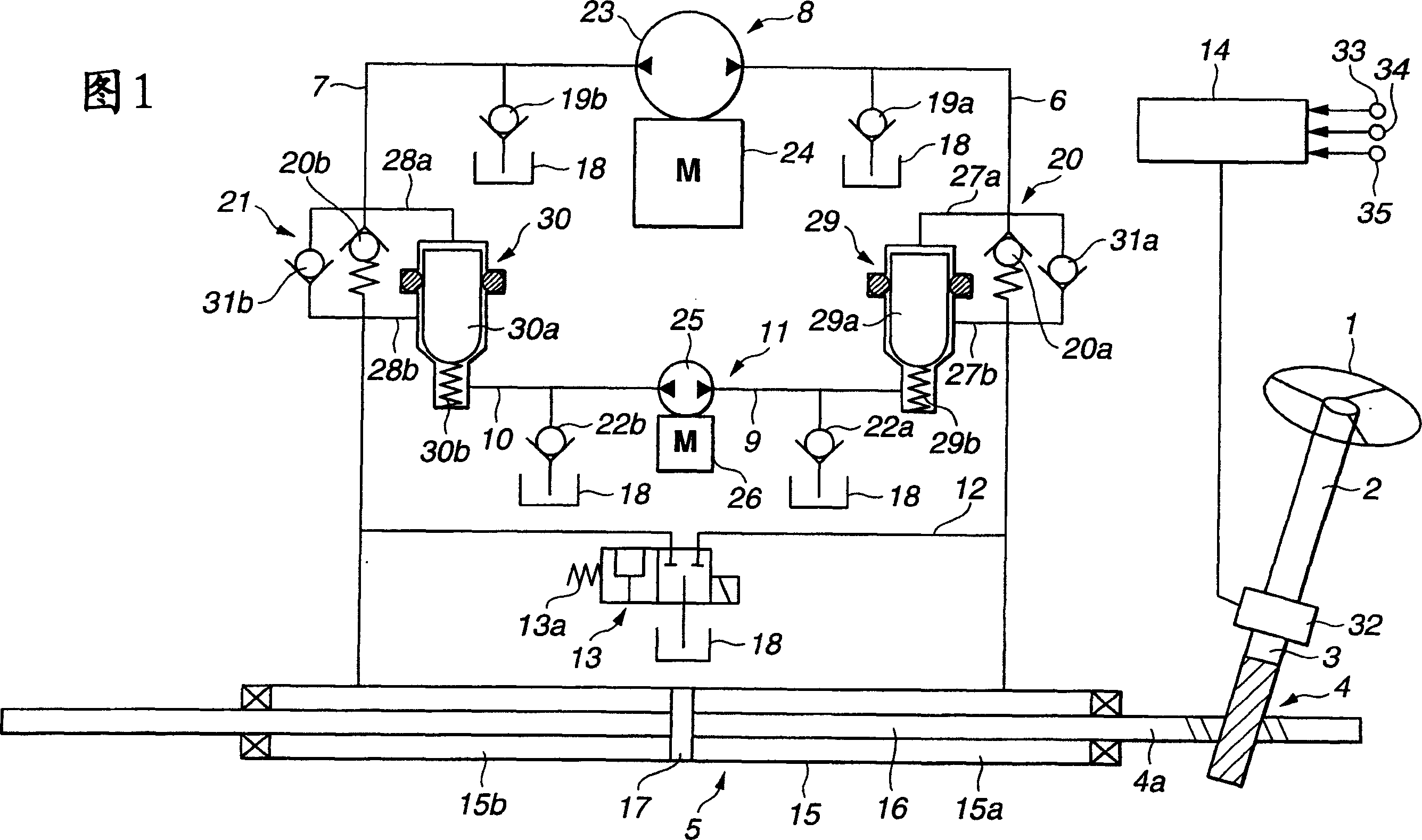
[0055]Fig. 1 schematically shows a power steering system of a first embodiment. The system of the first embodiment mainly consists of a steering shaft 2 fixedly connected to the steering wheel 1, a rack-and-pinion mechanism 4 mounted on an output shaft 3 connected to the lower end of the steering shaft 2 and serving as a steering mechanism (steering gear mechanism) , the hydraulic power cylinder 5 that provides assistance to the driver's force applied to the steering wheel, acts as the first hydraulic pressure that selectively provides the working fluid pressure to the hydraulic power cylinder 5 through the first fluid passage 6 or the second fluid passage 7 The first hydraulic supply mechanism 8 of the supply device is arranged parallel to the first hydraulic supply mechanism 8 and serves as a connection with the first and second fluid passages 6 and 7 respectively, and is arranged to be connected with the first and second fluid passages 6 and 7 The parallel third fluid chann...

no. 2 example

[0180] Referring now to Figure 15, there is shown a system of a second embodiment. The difference between the second embodiment and the first embodiment is that in the second embodiment, the capacities of the second electric motor 26 and the second trochoid pump 25 of the second hydraulic supply mechanism 11 are set to be equal to those of the first hydraulic pressure The capacity of the supply mechanism 8 is the same.

[0181] The second hydraulic supply mechanism 11 of the second embodiment is constituted in such a manner as to work together with the first hydraulic supply mechanism 8 during operation and during a failure in the first hydraulic supply mechanism. The sum of the maximum discharge capacities of the first and second hydraulic supply mechanisms 8 and 11 of the second embodiment is set substantially equal to the maximum discharge capacity of the first hydraulic supply mechanism 8 of the first embodiment. The discharge volume of each of the first and second hydrau...

no. 3 example

[0189] Referring now to Figure 17, there is shown a third embodiment of the system in which the communication passage 12 and the fail-safe valve 13 have been eliminated.

[0190] Thus, when both the first and second hydraulic pressure supply mechanisms 8 and 11 fail, the fail-safe valve function cannot be provided. This leads to the problem of an extremely large driver's operating load on the steering wheel 1 , but considerably reduces production costs.

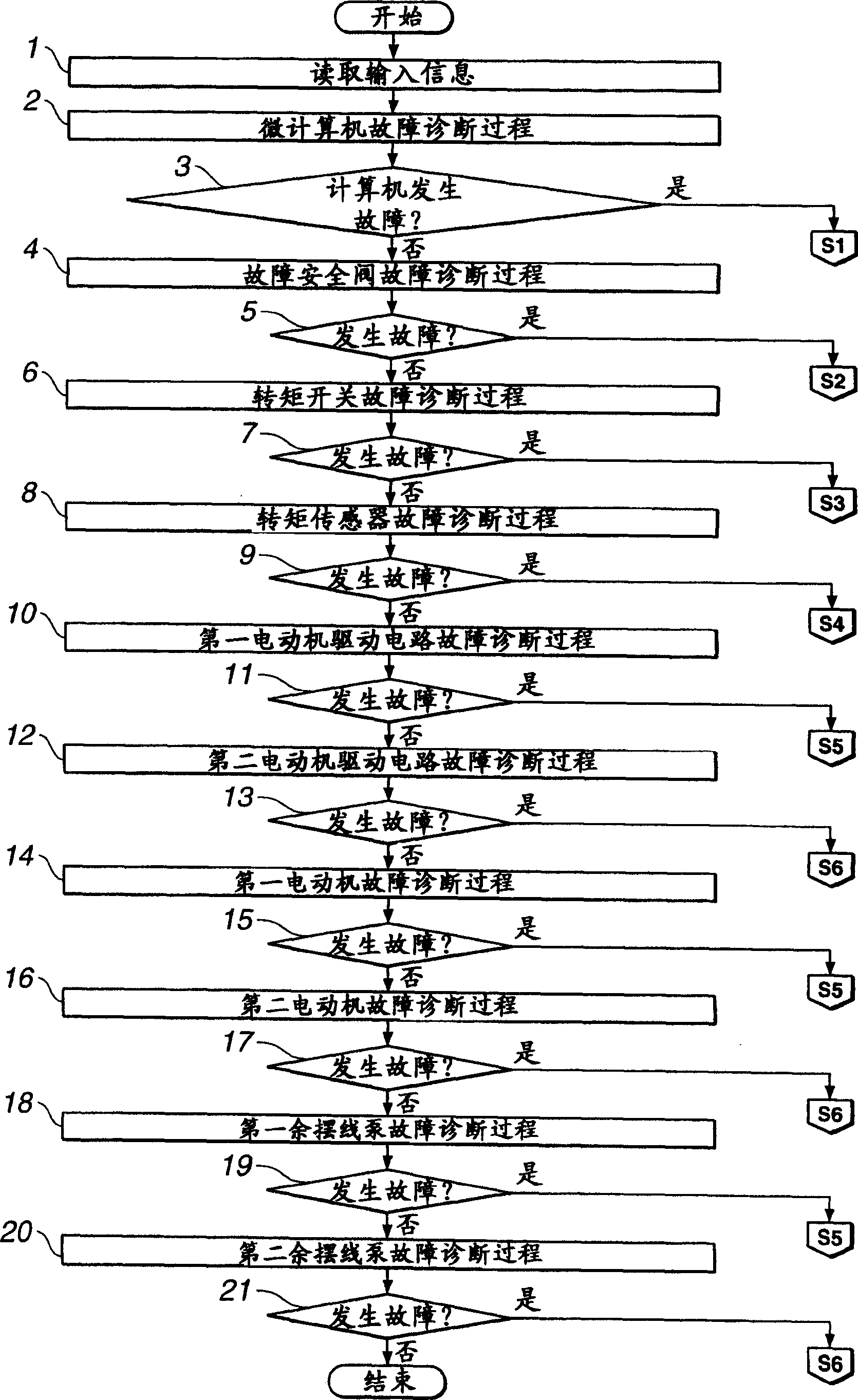
[0191] A failure detection method performed during a system failure such as a failure in at least one device constituting the power steering system of the third embodiment is the same as that of the first embodiment. In the system of the third embodiment, the fail-safe valve is removed, and then the fault detection method (other fault detection stages) other than the first stage S1 is applicable to the third embodiment.


PUM


Abstract

A power steering device, comprising a hydraulic power cylinder (5) assisting the steering force of a rack and pinion mechanism (4) and a first hydraulic pressure supply mechanism (8) having a first trochoid pump (23) and a first electric motor (24) selectively supplying hydraulic pressure to both hydraulic pressure chambers (15a) and (15b) through first and second passages (6) and (7). When the first hydraulic pressure supply mechanism fails, a second hydraulic pressure supply mechanism (11) selectively supplies working hydraulic pressure to both hydraulic pressure chambers through third and fourth passages (9) and (10) according to instruction signals from a control unit (14). Since a steering assist force is actively given to the rack and pinion mechanism (4) by the second hydraulic pressure supply mechanism (11), a steering wheel operating force given by a driver can be reduced.

Description

technical field [0001] The present invention relates to a power steering apparatus (power steering system) for applying steering assist by manipulating a hydraulic power cylinder in response to the magnitude of steering torque output from a steering mechanism of a motor vehicle, and more particularly to control of the power steering system method. Background technique [0002] A power steering system disclosed in the following patent application designated by "Document 1" is generally regarded as such a power steering system. [0003] The power steering system disclosed in this document consists of a steering shaft on which a steering wheel is mounted, an output shaft connected to the lower end of the steering shaft, mounted on the lower end of the output shaft, a rack-and-pinion mechanism for steering the steering wheels, and A rack-connected hydraulic power cylinder of a rack-and-pinion mechanism, and a reversible pump selectively supplying working fluid to a first hydrau...

Claims


Application Information

Patent Timeline
IPC IPC(8): B62D5/07B62D6/00
Inventor 佐佐木光雄横田忠治榊敏光平本三千也
Owner HITACHI LTD
Why Eureka
Try Eureka