Dynamic fin comprising coupled fin sections

a fin and coupled technology, applied in the field of dynamic fins, can solve the problems of increasing production efforts and costs, complicated manufacturing and assembly of components, and prone to contamination

Inactive Publication Date: 2011-03-17
VAN GELDER KLAAS BOUDEWIJN
View PDF3 Cites 19 Cited by
  • Summary
  • Abstract
  • Description
  • Claims
  • Application Information

AI Technical Summary

Problems solved by technology

Such a pin-hole hinge construction between adjacent fin sections brings some problems.
A first problem relates to the manufacturing of the fin sections.
Especially, in an embodiment of the dynamic fin for a surfboard, wherein the pin-hole hinge has to be very small, it may be a major problem to manufacture the hinge because of a limited available space for machining tools to access the fin.
The construction of the pin-hole is rather detailed which comp

Method used


Image

  • Dynamic fin comprising coupled fin sections
  • Dynamic fin comprising coupled fin sections
  • Dynamic fin comprising coupled fin sections

Examples


Embodiment Construction

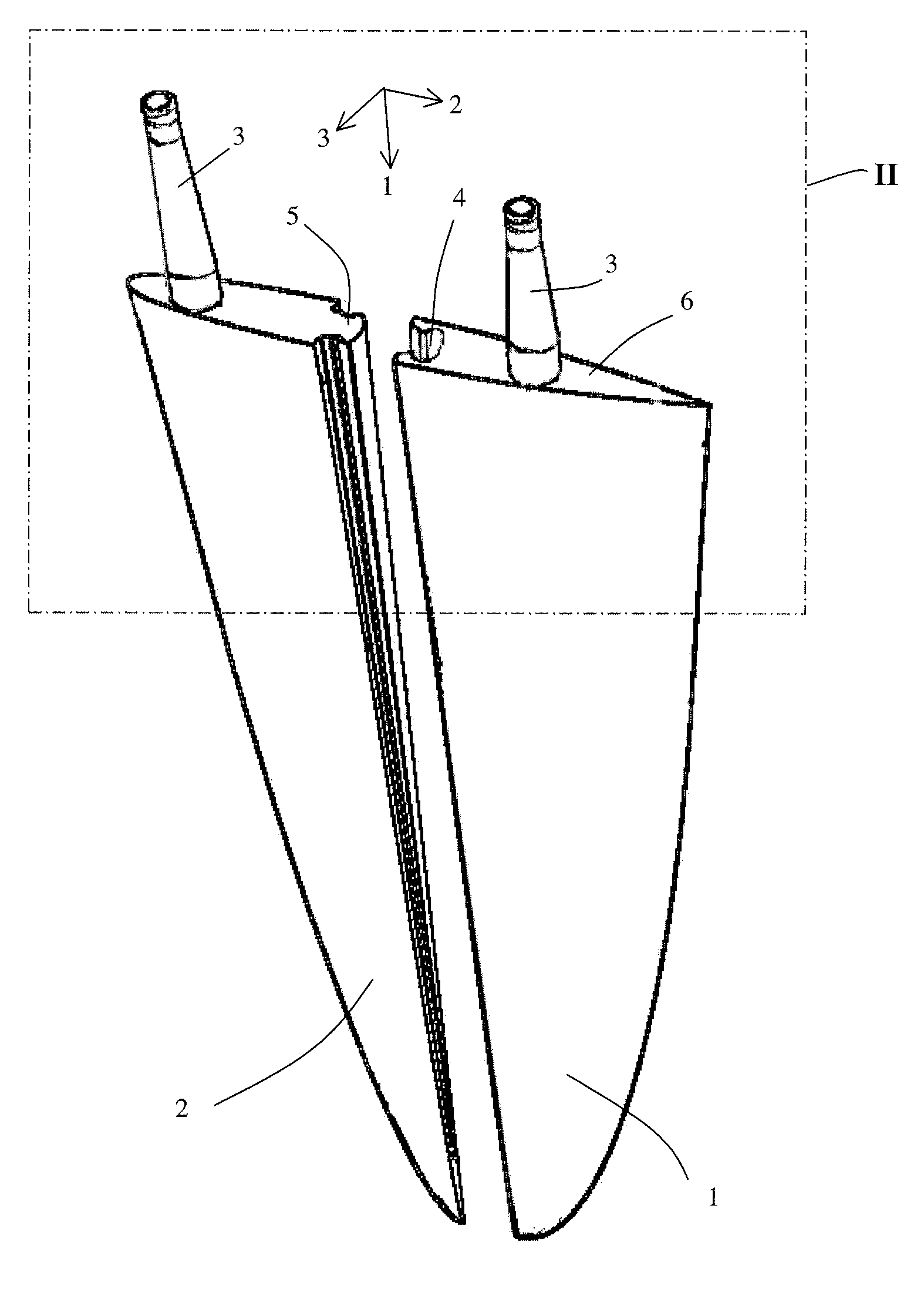
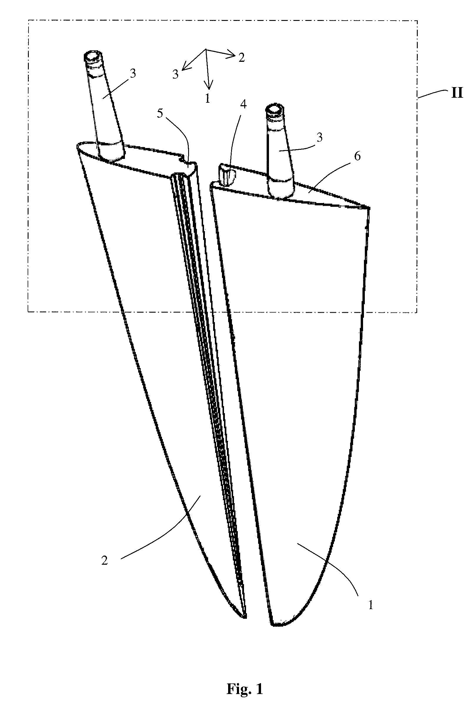
[0030]FIG. 1 shows a dynamic fin according to the invention. The dynamic fin is arranged as a fin which is suitable to serve as a fin for a surf board. The fin has outer side surfaces, a base and a tip. The outer side surfaces are substantially smooth. The dynamic fin comprises two parallelly arranged fin sections. For the application as a smart fin in a surfboard, the fin sections may be made from a plastic material including eventually reinforcing fibres. The fin sections are made sufficient rigid to withstand dynamic loads. The dynamic fin is formed by a first fin section which has a rounded front edge which defines a leading edge and forms a front side of the dynamic fin. The fin has a sharp edge at a tail which defines a trailing edge. During use a fluid may flow backwards along the fin from the rounded front side to the tail. The dynamic fin has a cross-section which is shaped like an airfoil having a chord which defines an upper chamber and a lower chamber.

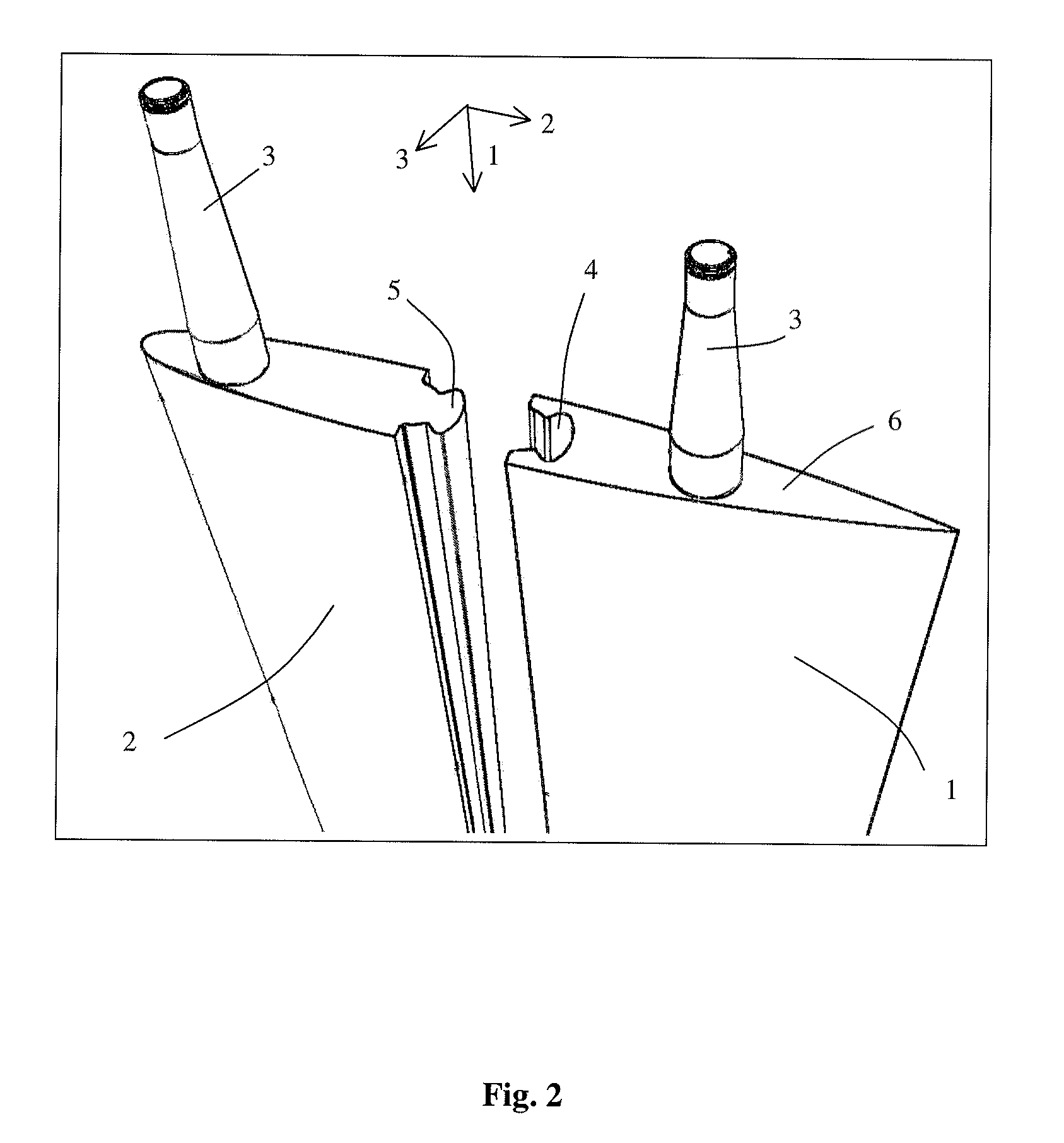
[0031]FIG. 2 shows ...


PUM


Abstract

A dynamic or aerodynamic fin comprising at least two parallel arranged fin sections. At least one fin section comprises a rotational axis for installing the fin section by a rotation shaft. An end stop is provided for stopping the rotational movement of the fin section to define an extreme position. In the extreme position the fin sections provide a substantially cambered shape to the fin. The dynamic fin is improved in that it comprises a pair of coupling elements. A first fin section is coupled to a second adjacent fin section by a pair of a first and second coupling elements. The first coupling element is complementary to the second coupling element. The first coupling element is part of, preferably integral, with the first fin section and the second coupling element is part of, preferably integral, with the second fin section.

Description

BACKGROUND OF THE INVENTION[0001]The present invention relates to a dynamic fin which comprises at least two parallel arranged fin sections. An orthogonal coordinate system including a first, second and third axis can be defined, wherein the fin sections extend in a direction of the first axis. Generally, this first direction is also regarded as the longitudinal direction. At least one fin section comprises a rotational axis for installing the fin section by a rotation shaft in for example a mounting box. The rotational axis extends in the direction of the fin section and enables a rotational movement of the fin section. An end stop is provided for stopping the rotational movement of the fin section to define an extreme position. In the extreme position the fin sections provide a substantially cambered shape to the fin. This cambered shape improves the hydro- or aerodynamic properties of the fin. In the other extreme position the fin may foam a mirrored cambered shape in comparison ...

Claims


Application Information

Patent Timeline
IPC IPC(8): F01D5/12B63B3/38B63H25/38B63H25/46B63H3/00
CPCB62D35/007B63B1/28B63B35/7926B63H1/26B63H25/38B64C3/48Y02T50/673B64C5/10B64C9/02F01D5/147F01D5/148F04D29/323Y02E10/727B64C5/06Y02T10/82Y02T50/60B63B32/66B63B32/64
Inventor VAN GELDER, KLAAS BOUDEWIJN
Owner VAN GELDER KLAAS BOUDEWIJN
Why Eureka
Try Eureka