Optical lens capable of rapid positioning

A technology of optical lenses and lenses, applied in the field of optical lenses, can solve the problems of cumbersome positioning of optical lenses, achieve fast and convenient positioning, and save costs

Inactive Publication Date: 2016-01-13
JIANGSU YONGXIN OPTICAL INSTR
View PDF4 Cites 0 Cited by
  • Summary
  • Abstract
  • Description
  • Claims
  • Application Information

AI Technical Summary

Problems solved by technology

[0006] The technical problem to be solved by the present invention is to provide an optical lens that can be assembled and positioned quickly, aiming at the defect of cumbersome positioning of the optical lens in the prior art

Method used


Image

  • Optical lens capable of rapid positioning
  • Optical lens capable of rapid positioning
  • Optical lens capable of rapid positioning

Examples


Embodiment Construction

[0019] The following briefly describes the content of the accompanying drawings used in the embodiments of the present invention, wherein:

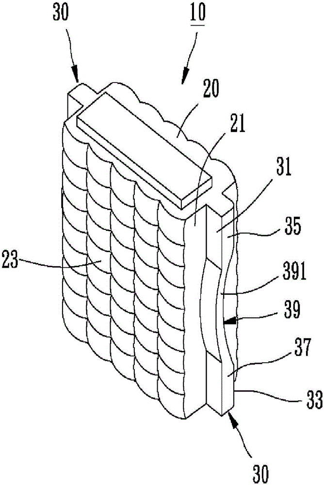
[0020] figure 1 It is a perspective view showing an optical lens according to a preferred embodiment of the present invention;

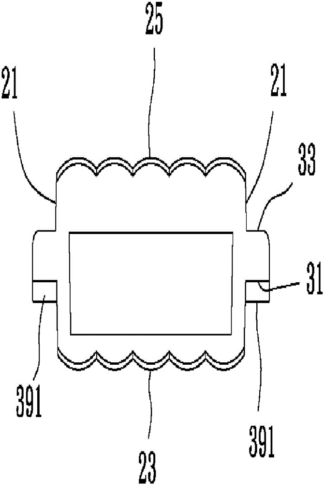
[0021] figure 2 It is a top view showing that the two positioning flanges of the optical lens of the preferred embodiment have protrusions;

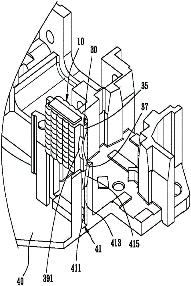
[0022] image 3 It is a three-dimensional exploded view showing that the optical lens of the preferred embodiment has not been installed in the projector body and the state of the insertion groove of the projector body; and

[0023] Figure 4 It is a three-dimensional view showing that the optical lens of the preferred embodiment is positioned in the groove of the projector body.

[0024] First please refer to Figure 1 to Figure 2 , the optical lens 10 provided by a preferred embodiment of the present invention mainly includes a lens body 20 and two positioning fla...


PUM


Abstract

The invention relates to an optical lens which can be installed in an optical machine body such as a projector. The optical lens mainly comprises a lens body and two positioning flanges which extend outwards integrally from two side surfaces of the lens body respectively and are capable of elastic deformation. The optical lens can be embedded into two embedding grooves which are formed in a machine body and spaced from each other via the positioning flanges and can be pressed to the wall surfaces of the embedding grooves tightly, thereby the optical lens can be assembled and positioned in the optical machine body conveniently and rapidly.

Description

technical field [0001] The present invention relates to an optical lens, in particular to an optical lens that can be quickly assembled and positioned in an optical body such as a projector. Background technique [0002] The installation and positioning of optical lenses in optical bodies such as projectors usually require high precision. Generally speaking, the commonly used positioning methods mainly include the following two types: [0003] 1. Fix the two sheet metal parts on the two sides of the optical lens respectively, then install the optical lens in the slot of the projector body, push the optical lens against the slot through the elasticity of the sheet metal itself the wall, to complete the positioning; and [0004] 2. First use the jig to make the optical lens lean against the wall of the groove, and then complete the positioning of the optical lens by dispensing glue. [0005] However, no matter whether the optical lens is positioned through the metal sheet o...

Claims


Application Information

Patent Timeline
IPC IPC(8): G02B7/02G03B21/14
CPCG02B7/022G03B21/142
Inventor 周国平
Owner JIANGSU YONGXIN OPTICAL INSTR
Why Eureka
Try Eureka