Numerical control machining clamping positioning device for shell part

A technology for positioning devices and parts, which is applied in positioning devices, metal processing equipment, metal processing machinery parts, etc., can solve the problems of low accuracy of clamping and positioning of shell parts, low stability of shell parts, and affecting the processing of shell parts Quality and other issues, to achieve the effect of precise position, fast and reliable clamping and positioning, and large range

Active Publication Date: 2020-05-29
正德职业技术学院
View PDF7 Cites 0 Cited by
  • Summary
  • Abstract
  • Description
  • Claims
  • Application Information

AI Technical Summary

Problems solved by technology

[0004] The purpose of the present invention is to solve the problem that the existing clamping and positioning device is not strong enough for clamping the shell parts, and can only clamp and position the shell parts of the same width and size, and the adaptability range of the work is small ;The clamping and positioning device has a low accuracy for clamping and positioning the shell parts; the area and range covered by the clamping of the shell parts are too small, resulting in extremely low stability of the shell parts when they are CNC machined, which seriously affects the shell parts. The quality of processing; the problem that the clamping and positioning device is not convenient and fast for the clamping and positioning of shell parts, and a numerically controlled machining clamping and positioning device for shell parts is proposed

Method used


Image

  • Numerical control machining clamping positioning device for shell part
  • Numerical control machining clamping positioning device for shell part
  • Numerical control machining clamping positioning device for shell part

Examples


Embodiment Construction

[0034]The technical solutions of the present invention will be clearly and completely described below in conjunction with the embodiments. Apparently, the described embodiments are only some of the embodiments of the present invention, not all of them. Based on the embodiments of the present invention, all other embodiments obtained by persons of ordinary skill in the art without creative efforts fall within the protection scope of the present invention.

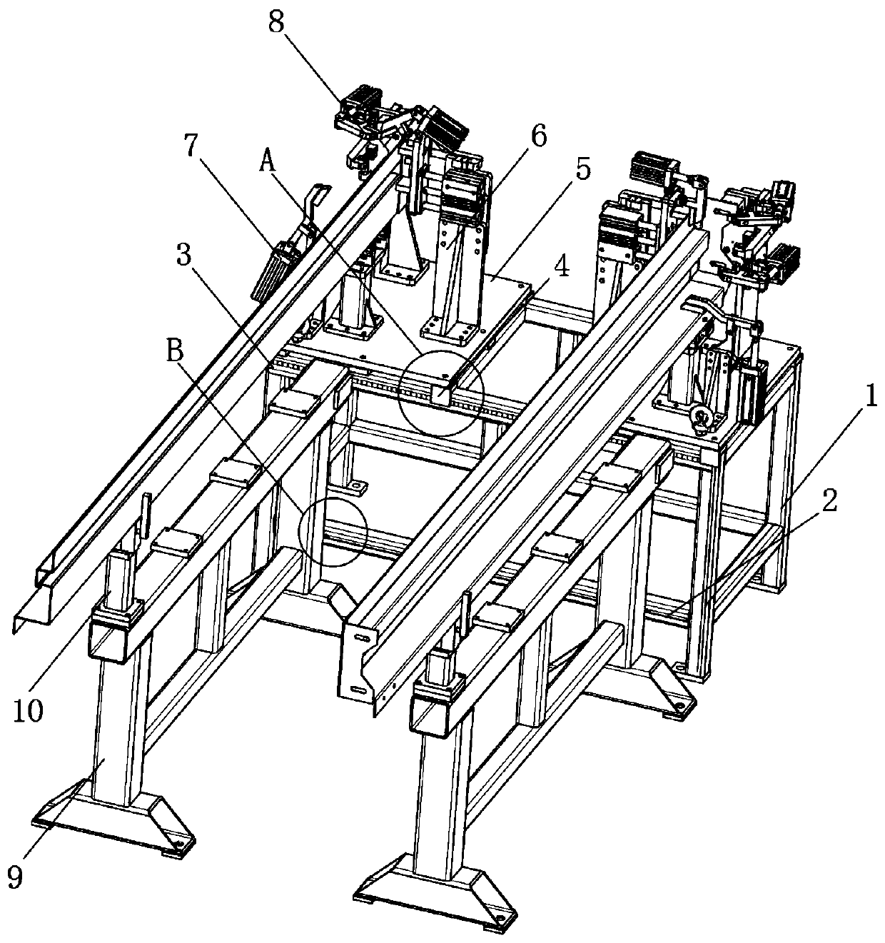
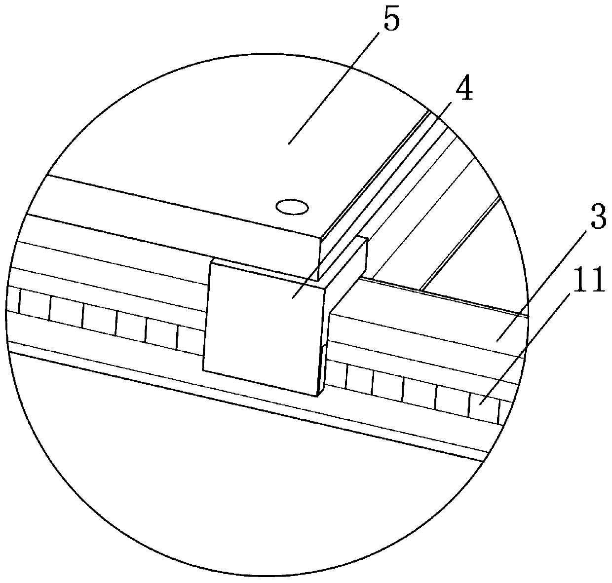
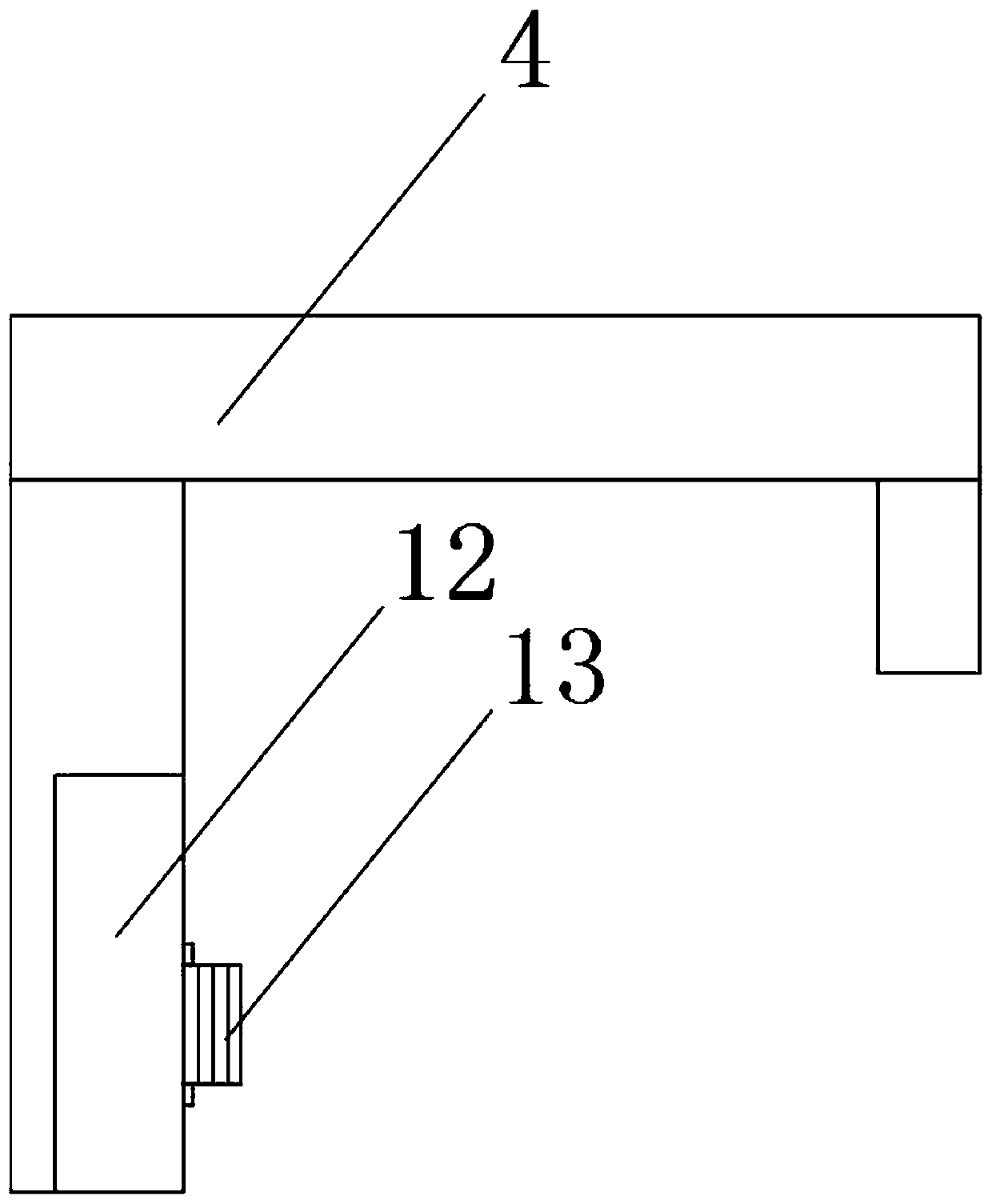
[0035] see Figure 1-8 As shown, a numerically controlled machining clamping and positioning device for shell parts includes a back support platform 1, two vertically arranged brackets 9 and an upper clamping seat 10, and the top of the back support platform 1 is horizontally arranged. In addition, a lower sleeve rod 2 with a hollow cuboid structure is horizontally arranged under one side of the rear support platform 1, and two upper clamping rails 3 are arranged in parallel above the lower sleeve rod 2, and the two upper cl...


PUM


Abstract

The invention discloses a numerical control machining clamping positioning device for a shell part. The device comprises a rear supporting table, two vertically-arranged carrying frames and an upper clamping base, wherein the upper portion of the rear supporting table is horizontally arranged, lower loop bars of hollow cuboid structures are horizontally arranged at the lower portion of one side ofthe rear supporting table, and two upper clamping rails are arranged at the upper portions of the lower loop bars in parallel. The device has the beneficial effects that a hydraulic cylinder III pushes a hinge I and an overturning pressing block I to turn over through a hydraulic shaft III, the overturning pressing block I turns over around a hinge II, the shell part is clamped and positioned through one end of the overturning pressing block I, it is guaranteed that the shell part is clamped and positioned on the device more firmly, two clamping rods on an upper clamping base are adjusted left and right to move, it is guaranteed that the device can adapt to and clamp shell parts of different widths, a hydraulic cylinder II pushes a pushing and clamping plate to move left and right, the overturning pressing block I is adjusted in an overturning mode, and it is guaranteed that the device is more accurate and firmer in clamping and positioning the shell parts of different widths and sizes.

Description

technical field [0001] The invention relates to a clamping and positioning device, in particular to a numerically controlled processing clamping and positioning device for shell parts, belonging to the technical field of clamping and positioning devices. Background technique [0002] There are many kinds of shell parts, such as the side wall of the car shell, electrical shell components, etc. During the CNC machining process of the shell parts, the clamping and positioning device is indispensable, and the shell parts are clamped by the clamping and positioning device Fixed to ensure that the shell parts are more stable and reliable when being processed, and improve the precision of the shell parts being processed. [0003] There are still many deficiencies in the existing NC machining positioning device for shell parts in use. The existing clamping and positioning device is not firm enough for shell parts, and can only be used for the same width, The clamping and positionin...

Claims


Application Information

Patent Timeline
Patent Type & Authority Applications(China)
IPC IPC(8): B23Q3/08
CPCB23Q3/062B23Q3/082
Inventor 赵寿宽龚君
Owner 正德职业技术学院
Why Eureka
Try Eureka