
A power-on delay circuit of a liquid crystal display and a liquid crystal display

A technology of delay circuit and LCD screen, applied in nonlinear optics, static indicator, optics, etc., can solve the problems of LCD screen flickering or displaying white light, increasing inrush current, unstable power-on voltage of LCD screen, etc. Achieve the effect of avoiding snowflake points, filtering current clutter, and ensuring stability

Active Publication Date: 2018-05-29
MIANYANG HKC OPTOELECTRONICS TECH CO LTD
View PDF5 Cites 0 Cited by
  • Summary
  • Abstract
  • Description
  • Claims
  • Application Information

AI Technical Summary

Problems solved by technology

[0004] The purpose of the embodiments of the present invention is to provide a power-on delay circuit of a liquid crystal screen and a liquid crystal screen, aiming at solving problems such as voltage instability and surge current increase at the moment of power-on of the liquid crystal screen, which cause the liquid crystal screen to flicker instantly or display white light. The problem of the phenomenon

Method used


Image

  • A power-on delay circuit of a liquid crystal display and a liquid crystal display
  • A power-on delay circuit of a liquid crystal display and a liquid crystal display
  • A power-on delay circuit of a liquid crystal display and a liquid crystal display

Examples


Embodiment Construction

[0024] In order to make the object, technical solution and advantages of the present invention clearer, the present invention will be further described in detail below in conjunction with the accompanying drawings and embodiments. It should be understood that the specific embodiments described here are only used to explain the present invention, not to limit the present invention.

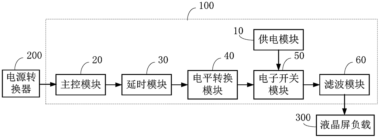
[0025] figure 1 It is a basic structural block diagram of a power-on delay circuit of a liquid crystal display provided by an embodiment of the present invention.

[0026] Such as figure 1 As shown, the power-on delay circuit 100 of the liquid crystal screen provided by the embodiment of the present invention is connected between the power converter 200 and the load 300 of the liquid crystal screen, and the power-on delay circuit 100 of the liquid crystal screen includes:

[0027] A power supply module 10 connected to the power converter to input electric energy;

[0028] The main control module...


PUM


Abstract

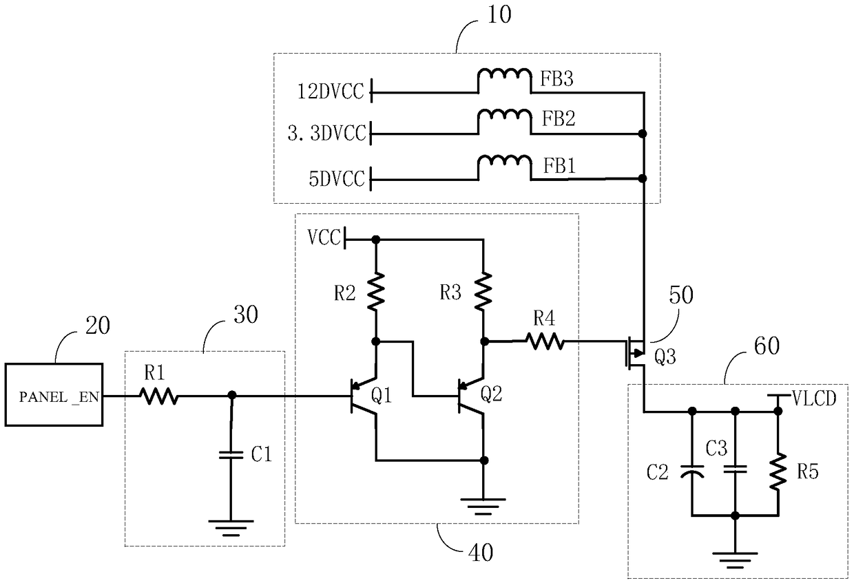
The invention is adapted to the field of liquid crystal displays and provides a power-up delay circuit of a liquid crystal display and the liquid crystal display. The power-up delay circuit of the liquid crystal display comprises a power module used for inputting electric energy, a master control module used for inputting high / low level signals, a delay module connected with the master control module in order to control a power-up delay time loaded with the liquid crystal display, a level switch module used for level switch of high / low level signals outputted by the master control module and an electronic switch module controlled by the level switch module in order to connect or disconnect. An input end of the electronic switch module is connected with the power module. A control end the electronic switch module is connected with an enable end of the level switch module. An output end the electronic switch module is connected with a load of the liquid crystal display. The power-up delay circuit of the liquid crystal display and the liquid crystal display have following beneficial effects: due to the fact that the control end used for outputting high / low level signals and the delay module, the level switch module and the electronic switch module matching the master control circuit are arranged on the master control circuit, power-up delay control over the liquid crystal display is achieved in order to avoid splash-screen or white-light display and other undesirable phenomena caused by direct power-up of liquid crystal display.

Description

technical field [0001] The invention belongs to the field of liquid crystal display screens, in particular to a power-on delay circuit of the liquid crystal screen and the liquid crystal screen. Background technique [0002] LCD screens or LCD TVs with LCD screens mainly convert the mains power into direct current through a power converter to supply the LCD screen to realize the display function of the LCD screen. [0003] However, most of the LCD screens or LCD TVs with LCD screens currently on the market convert the mains power into DC power through a power converter, and then directly supply power to the LCD screen. This makes the voltage of the LCD screen unstable at the moment of power-on, and the surge current increases, causing the LCD screen to flicker or display white light and other undesirable phenomena. Contents of the invention [0004] The purpose of the embodiments of the present invention is to provide a power-on delay circuit of a liquid crystal screen an...

Claims


Application Information

Patent Timeline
Patent Type & Authority Patents(China)
IPC IPC(8): G02F1/133
CPCG02F1/13306
Inventor 王智勇曾吉林
Owner MIANYANG HKC OPTOELECTRONICS TECH CO LTD
Learn More