Wire bridge

A wire and bridge technology, applied in the field of wire bridge, can solve the problems of easy deformation of side plates and cover plates, unfavorable maintenance, labor-intensive and time-consuming installation and disassembly, etc. The effect of overhaul

Inactive Publication Date: 2016-01-13
广西资优电气设备有限公司
View PDF4 Cites 6 Cited by
  • Summary
  • Abstract
  • Description
  • Claims
  • Application Information

AI Technical Summary

Problems solved by technology

However, the load-bearing strength of the traditional bridge and the heat dissipation effect of the laid wires or cables are not ideal.
Ordinary bridges are made of steel plates that are bent into grooves, and then the wires and cables are placed in the grooves, and then a cover is added on it. The bridges with this structure have poor heat dissipation and use more materials, which increases the cost, waste of materials
In addition, the current traditional cable bridge uses a cover plate on the main body of the bridge frame. The cover plate and the main body of the bridge frame are generally connected by bolts. After the connection, the seal is not tight, and it is inevitable that dust, rain, moisture or direct heat, etc., the cables located in the bridge are easily damaged, and the cable bridge cannot protect the cables well, and for longer cable bridges , the side panels and cover panels of the bridge are easily deformed and damaged
[0003] At the same time, most of the bridges in the prior art are single-layer structures, which cannot properly arrange cables and wires in layers, which is not conducive to later maintenance

Method used


Image

  • Wire bridge
  • Wire bridge
  • Wire bridge

Examples


Embodiment Construction

[0021] The preferred embodiments of the present invention will be described in detail below with reference to the accompanying drawings, so that the advantages and features of the present invention can be more easily understood by those skilled in the art, and the protection scope of the present invention can be more clearly defined.

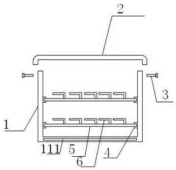
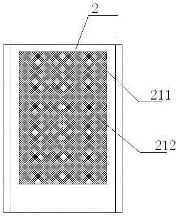
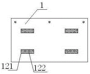
[0022] refer to figure 1 , figure 2 , image 3 and Figure 4 The shown wire bridge includes a mounting base 1 and an end cover 2. The two sides of the end cover 2 are vertically bent downwards to form a wrapping edge, and the wrapping fits on both sides of the top of the mounting base 1 Position, between the mounting seat 1 and the end cover 2 is fitted with a screw 3, the interior of the mounting seat 1 is symmetrically provided with more than two card seats 4, and the two symmetrically provided card seats 4 A wire laying board 5 is fitted between them, and a threaded hole 501 is provided at a position close to both ends of the wire laying ...


PUM


Abstract

The invention discloses a wire bridge, which comprises a mounting base and an end cover, wherein two sides of the end cover are vertically bent downwards and then form covered edges; the covered edges are matched at the positions of two sides of the top of the mounting base; screws are matched between the mounting base and the end cover; more than two clamping seats are symmetrically arranged in the mounting base; and wire pavement boards are matched between the two symmetrically arranged clamping seats; threaded holes are formed in the positions, close to two ends of the wire pavement boards; an L-shaped buckling part is arranged in each threaded hole; and hollow-out grooves are formed in the bottom of the mounting base. According to the device, the wall thickness of the mounting base can be reduced through the hollow-out grooves; heat dissipation is facilitated; heat accumulation is avoided; sheath oxidation of cables or wires is avoided; meanwhile, layered placement of the cables and the wires can be achieved through the wire pavement boards; and late maintenance is facilitated. Meanwhile, individual buckling of the wires with different purposes can be achieved through the buckling parts, so that late searching and stripping are facilitated.

Description

technical field [0001] The invention relates to an electric wire bridge. Background technique [0002] At present, in the field of power supply and distribution technology in our country, the bridge is a bracket used to bear wires or cables. However, the load-bearing strength of the traditional bridge and the heat dissipation effect of the laid wires or cables are not ideal. Ordinary bridges are made of steel plates that are bent into grooves, and then the wires and cables are placed in the grooves, and then a cover is added on it. The bridges with this structure have poor heat dissipation and use more materials, which increases the Cost, resulting in waste of materials. In addition, the current traditional cable bridge uses a cover plate on the main body of the bridge frame. The cover plate and the main body of the bridge frame are generally connected by bolts. After the connection, the seal is not tight, and it is inevitable that dust, rain, moisture or direct heat, etc...

Claims


Application Information

Patent Timeline
Patent Type & Authority Applications(China)
IPC IPC(8): H02G3/04
Inventor 蒙国珊
Owner 广西资优电气设备有限公司
Why Eureka
Try Eureka