
A busbar floating conical mirror polishing device

A technology of polishing device and conical mirror, which is applied in grinding drive device, grinding/polishing equipment, optics, etc., can solve the problems of low price, incapable of polishing disc, no design of conical mirror polishing machine, etc., and meet the requirements of lowering , wear uniformity, ensure the effect of stability

Active Publication Date: 2017-11-07
SHANGHAI MODERN ADVANCED ULTRA PRECISION MFG CENT
View PDF6 Cites 0 Cited by
  • Summary
  • Abstract
  • Description
  • Claims
  • Application Information

AI Technical Summary

Problems solved by technology

The processing of optical parts is closely dependent on the processing equipment used to manufacture it. The above commonly used polishing equipment for optical parts is generally a single-axis or multi-axis flat polishing machine, spherical polishing machine, cylindrical polishing machine, etc. These equipments are very mature and low in price. It has stable performance and is used by most optical processing enterprises, but the cone mirror is very special. Traditional processing equipment cannot complete the polishing of this part. The current price is relatively low. There is no cone mirror polishing machine suitable for enterprise production. designed for sale
[0005] One of the difficulties in polishing cone mirrors is that there is no special equipment, which stems from the special shape of cone mirrors. General optical parts, such as plane mirrors and spherical mirrors, have infinitely many polishing axes, and the curvature radius of any area on the part is equal , such characteristics make the equipment for processing it very simple, that is, the workpiece rotates, and the polishing disc uses a surface-shaped die disc with the same curvature radius of the part (flat mirror for flat mirrors, spherical mirror for spherical mirrors), on the surface of the workpiece. Swing left and right, and add polishing liquid on the surface of the workpiece at the same time to polish the plane mirror and spherical mirror. But the cone mirror has only one optical axis, and the curvature radius of each point on the surface is different along the optical axis direction, that is, its parent surface is a straight line , but each point adjacent to the busbar is a torus, which causes the workpiece in the polishing equipment to rotate, but the polishing disc cannot swing, and the polishing disc cannot be any fixed curvature.

Method used


Image

  • A busbar floating conical mirror polishing device

Examples


Embodiment Construction

[0024] The present invention will be further described below in conjunction with the accompanying drawings and specific embodiments.

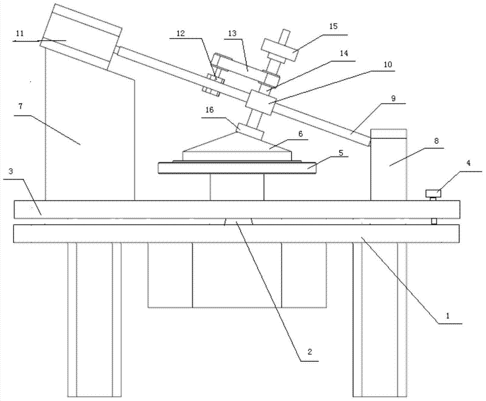
[0025] according to figure 1 A busbar floating conical mirror polishing device shown includes a power system, a busbar floating system and a polishing system. The power system includes a power frame 1, and the conical power shaft 2 of the power frame 1 extends out of the table to connect the workpiece The turntable 5 and the tapered power shaft 2 drive the workpiece turntable 5 to rotate. For the transformation of the power frame 1 that can provide rotating power, only the table surface that the tapered power shaft 2 protrudes out of the frame is guaranteed.

[0026] The busbar floating system includes a floating disc 5 suspended on the power rack table. The center of the floating disc 5 has an avoidance hole for avoiding the tapered power shaft 3. The two sides of the floating disc 5 are provided with guide rail supports, which are respective...


PUM


Abstract

The invention relates to a busbar floating type polishing device for a conscope. The busbar floating type polishing device comprises a power system, a busbar floating system and a polishing system. The power system comprises a power rack. A conical power shaft of the power rack stretches out of a tabletop and is connected with a workpiece rotary disc. The conical power shaft drives the workpiece rotary disc to rotate. The busbar floating system comprises a floating disc suspended on the tabletop of the power rack. An avoiding hole avoiding the conical power shaft is formed in the center of the floating disc. Guide rail supports are arranged on the two sides of the floating disc. An inclined busbar polishing guide rail is fixed between the guide rail supports. A busbar movement driving motor used for driving the polishing system to reciprocate is arranged on the busbar polishing guide rail. The polishing system comprises a polishing shaft perpendicular to the busbar polishing guide rail. A polishing disc is fixed to the tail end of the polishing shaft and is driven by a polishing disc driving motor to rotate. The busbar floating type polishing device has the beneficial effects that a workpiece is repeatedly installed and positioned accurately, and the production efficiency is improved; and the structure is simple, manufacturing cost is low, and use is convenient.

Description

technical field [0001] The invention relates to an optical polishing mechanical device, in particular to a busbar floating conical mirror polishing device. Background technique [0002] Cone mirror is an optical part shaped like a standard cone. It is often used in beam shaping in optical systems. It can shape a circular beam into a circular beam. Such a beam is very useful in specific applications, such as In the integrated circuit lithography machine, it can improve the resolution of lithographic lines, and then achieve the key role of improving the integration of integrated circuits. [0003] It is very difficult to manufacture, especially polish, metal cone mirrors with low requirements, which can generally be manufactured by turning or grinding. But for the cone mirror of optical glass material used in high-end applications, the grinding method only belongs to the rough machining of this kind of parts, and the real manufacturing difficulty lies in the polishing process...

Claims


Application Information

Patent Timeline
Patent Type & Authority Patents(China)
IPC IPC(8): B24B13/00B24B13/005B24B47/12
CPCB24B13/00B24B13/0055B24B47/12
Inventor 魏向荣蒋权泉黄克飞李淑芝
Owner SHANGHAI MODERN ADVANCED ULTRA PRECISION MFG CENT
Learn More