
Manual detection auxiliary device for continuous production line of tubular products or bars

A technology of manual detection and auxiliary devices, which is applied in the direction of transportation and packaging, conveyors, mechanical conveyors, etc., can solve the problems of difficult arrangement of artificial tube/bar detection stations, affecting the production rhythm of the production line, and the arrangement of detection stations. , to achieve the effect of saving working time, improving production efficiency and reducing space constraints

Active Publication Date: 2016-01-20
TIANJIN SERI MACHINERY EQUIP
View PDF9 Cites 6 Cited by
  • Summary
  • Abstract
  • Description
  • Claims
  • Application Information

AI Technical Summary

Problems solved by technology

[0002] In the metallurgical tube / bar continuous production line, it is often necessary to arrange online artificial tube / bar inspection stations in the process. Due to space constraints, the inspection stations can generally only be arranged on both sides of the production line, so that the pipes and bars can be offline for a short time detection
This arrangement often affects the production rhythm of the production line and reduces production efficiency
In addition, if the inspection station cannot be arranged on both sides of the production line due to the limitation of the workshop space, it will be difficult to arrange the artificial tube / bar inspection station

Method used


Image

  • Manual detection auxiliary device for continuous production line of tubular products or bars
  • Manual detection auxiliary device for continuous production line of tubular products or bars
  • Manual detection auxiliary device for continuous production line of tubular products or bars

Examples


Embodiment Construction

[0025] In order to further understand the invention content, characteristics and effects of the present invention, the following examples are given, and detailed descriptions are as follows in conjunction with the accompanying drawings:

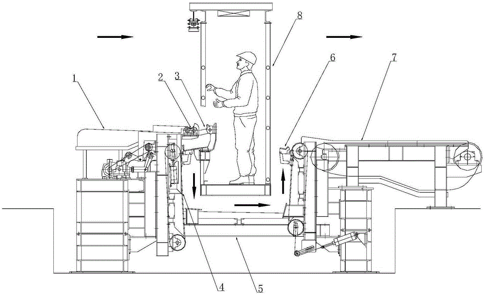
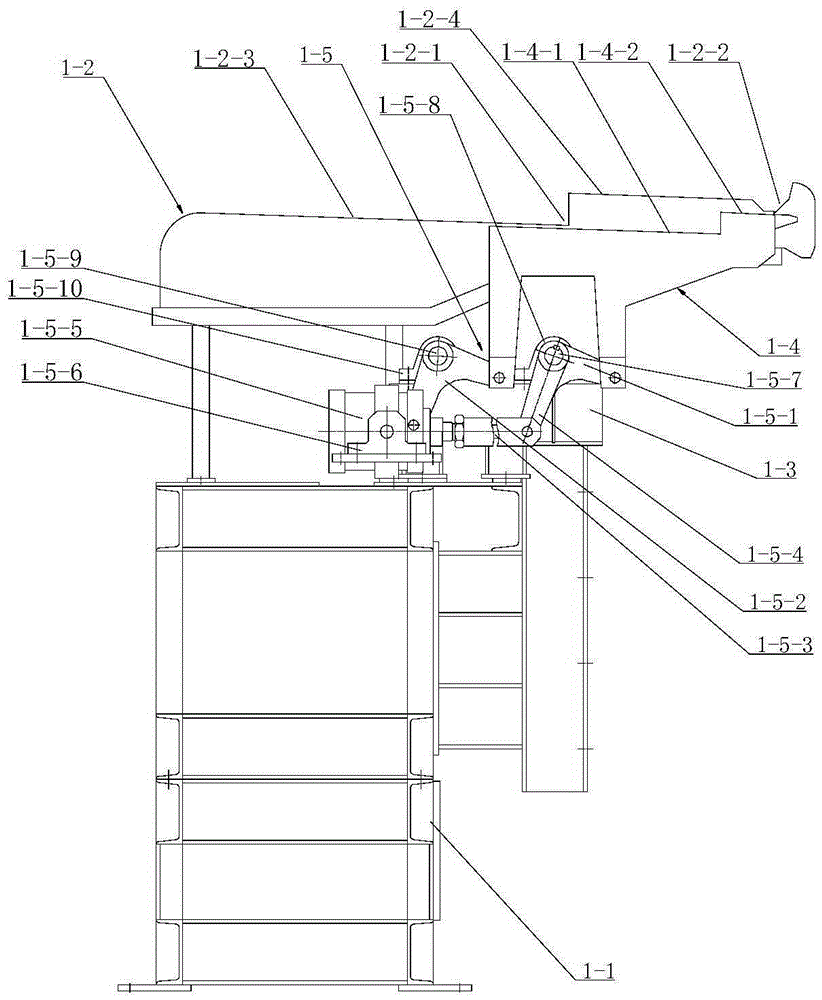
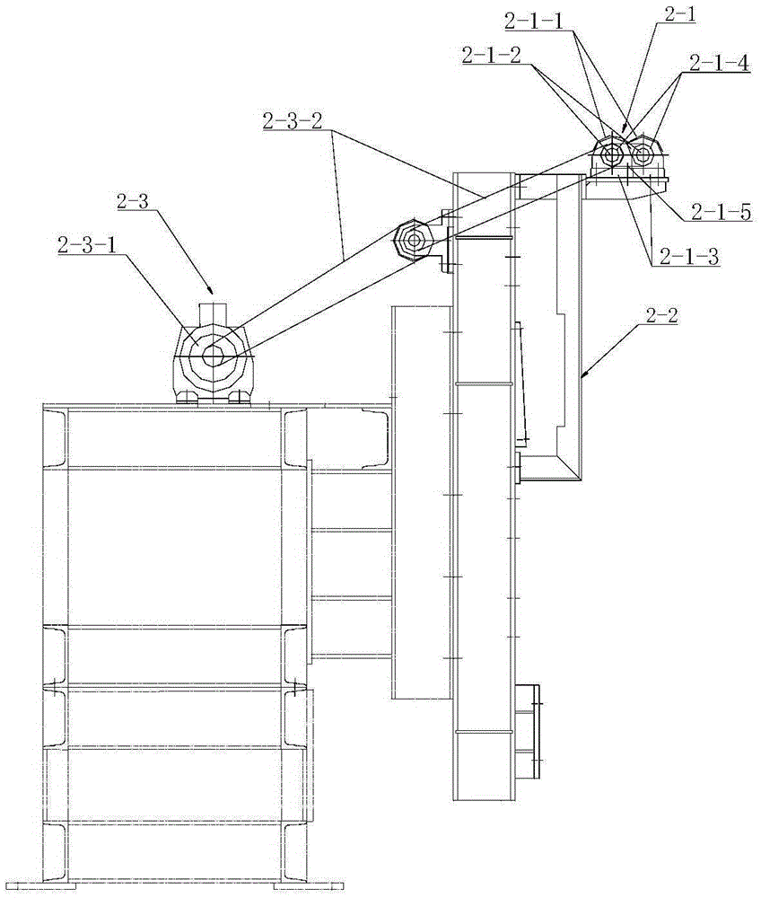
[0026] see Figure 1-9 , used for the manual detection auxiliary device on the continuous production line of pipes or rods. According to the conveying direction of the material, the manual auxiliary device includes a feeding mechanism 1, a detection wheel mechanism 2, a feeding mechanism 3, and a descending transmission mechanism 4 connected in sequence. , material transport mechanism 5, ascending conveying mechanism 6, material discharging mechanism 7, wherein a manual operation platform 8 is provided between the descending conveying mechanism and the ascending conveying mechanism, the manual operating platform is positioned at the top of the conveying mechanism, and the manual operating platform consists of The bracket 8-1, the top frame 8-...


PUM


Abstract

The invention provides a manual detection auxiliary device for a continuous production line of tubular products or bars. In a material conveying direction, the manual detection auxiliary device comprises a loading mechanism, a detecting wheel-aligning mechanism, an unloading mechanism, a falling transporting mechanism, a material handling mechanism, a rising transporting mechanism and a discharge mechanism, all of which are orderly connected together, wherein a manual operating platform is arranged between the falling transporting mechanism and the rising transporting mechanism and located above the material handling mechanism; an upper frame is arranged at an upper end portion of the manual operating platform; a lighting lamp is mounted on the upper frame and the upper frame is provided with a movable lifting hook for suspending detection aids. By means of the manual detection auxiliary device, a detected tubular product or bar is drawn through below the manual operation platform, and therefore, space limitation is reduced, and a production rhythm of the production line is accelerated and the production efficiency is improved. Meanwhile, various necessary tools used for operations such as detection and coping can be suspended on the movable lifting hook of the manual operating platform and can be picked up by the detection personnel for use conveniently, and therefore, the working time can be saved.

Description

technical field [0001] The invention relates to the technical field of pipe / rod production, in particular to a manual detection auxiliary device used in a continuous production line of rods or pipes. Background technique [0002] In the metallurgical tube / bar continuous production line, it is often necessary to arrange online artificial tube / bar inspection stations in the process. Due to space constraints, the inspection stations can generally only be arranged on both sides of the production line, so that the pipes and bars can be offline for a short time detection. This arrangement often affects the production rhythm of the production line and reduces production efficiency. In addition, if the inspection station cannot be arranged on both sides of the production line due to the limitation of the workshop space, it will be difficult to arrange the artificial tube / bar inspection station. Contents of the invention [0003] In order to solve the technical problems existing ...

Claims


Application Information

Patent Timeline
Patent Type & Authority Applications(China)
IPC IPC(8): B65G47/248B65G17/12B65G37/00
Inventor 徐金凤杨丽珍钟少振
Owner TIANJIN SERI MACHINERY EQUIP
Learn More