Supercharge Your Innovation With Domain-Expert AI Agents!

Stamping strip clamping device

A material clip and clamping part technology, which is applied in the field of stamping strip material clamping device, can solve the problems of poor feeding, inaccurate feeding, affecting product quality and output, etc., and achieve the effect of smooth feeding and convenient adjustment

Inactive Publication Date: 2016-01-20
JIANGSU SUN WAY GRP FEIDA CO LTD
View PDF5 Cites 0 Cited by
  • Summary
  • Abstract
  • Description
  • Claims
  • Application Information

AI Technical Summary

Problems solved by technology

[0002] When the coiled strip material is conveyed to the stamping die by the feeder, because there is a certain distance between the feeder and the entrance of the mold, the strip material sags due to its own weight, resulting in poor feeding during stamping and inaccurate feeding, which affects the quality and output of the product

Method used


Image

  • Stamping strip clamping device
  • Stamping strip clamping device

Examples


Embodiment Construction

[0013] In order to make the above objects, features and advantages of the present invention more comprehensible, the present invention will be further described in detail below in conjunction with the accompanying drawings and specific embodiments.

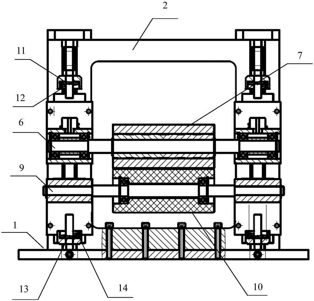
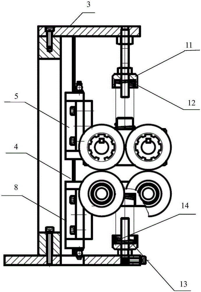
[0014] like figure 1 and figure 2 As shown, the stamping strip clamping device in this embodiment includes a bottom plate 1, an upright plate 2, a connecting plate 3, a first linear guide rail 4, a second linear guide rail (not shown), an upper clamping portion and a lower clamping The upright plate 2 is a back-shaped rectangular plate with a hole in the middle, one end of the upright plate 2 is fixedly connected to the bottom plate 1, and the other end of the upright plate 2 is fixedly connected to the connecting plate 3 ; The first linear guide rail 4 and the second linear guide rail (not shown) are arranged in parallel on both sides of the upright plate 2;

[0015] The upper clamping part includes a first upper slider 5, a s...


PUM


Abstract

The invention provides a stamping strip clamping device which comprises a bottom plate, a vertical plate, a first linear guide rail, a second linear guide rail, an upper clamping portion and a lower clamping portion. One end of the vertical plate is fixed to the bottom plate. The first linear guide rail and the second linear guide rail are arranged on the two sides of the vertical plate in parallel. The upper clamping portion comprises a first upper sliding block, a second upper sliding block and an upper pulley assembly. The lower clamping portion comprises a first lower sliding block, a second lower sliding block and a lower pulley assembly. According to the stamping strip clamping device, the influence caused due to the fact that stamping strips droop at the front end of a die in the feeding process on feeding is eliminated, adjustment of the strip clamping height and clamping force is achieved, and thus feeding is smoother.

Description

technical field [0001] The invention relates to the field of mechanical equipment, in particular to a stamping strip clamping device. Background technique [0002] When the coiled strip material is conveyed to the stamping lower die by the feeder, because there is a certain distance between the feeder and the entrance of the mold, the strip material sags due to its own weight, resulting in poor feeding during stamping and inaccurate feeding, which affects the quality and output of the product . Contents of the invention [0003] In view of the above problems, the present invention provides a stamping strip clamping device, which eliminates the influence of the stamping strip on the feeding due to its own weight at the front end of the die, and realizes the clamping height and clamping of the strip. The adjustment of the holding force makes the feeding more smooth. [0004] According to the technical solution of the present invention: a clamping device for stamping strips...

Claims


Application Information

Patent Timeline
Patent Type & Authority Applications(China)
IPC IPC(8): B65G47/90
Inventor 杨进朱维东杨煜
Owner JIANGSU SUN WAY GRP FEIDA CO LTD
Features
  • R&D
  • Intellectual Property
  • Life Sciences
  • Materials
  • Tech Scout
  • Unparalleled Data Quality
  • Higher Quality Content
  • 60% Fewer Hallucinations
Learn More