[0051] The preferred embodiments of the present invention will be described in detail below with reference to the accompanying drawings.
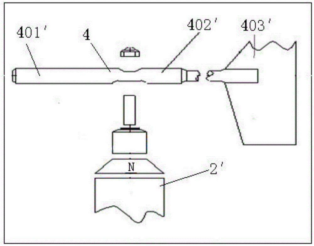
[0052] In order to achieve the purpose of the present invention, such as Figure 4 to 6 As shown, the wind vane zero position correction device of the present invention includes a wind vane angle correcting component 1, a spindle angle correcting component 2 and an angle adjusting component. The wind vane angle correcting component 1 is installed outside the testing device 3 and is connected to the wind vane 10 on the testing device 3. Connected, the wind vane angle correction component 1 is used to adjust the angle of the wind vane 10; the spindle angle correction component 2 is installed on the spindle 5 in the testing device 1, and the spindle angle correction component 2 is used to measure the angle of the spindle 5; the angle adjustment components are respectively connected to the wind vane The main shaft angle correcting components 1 and 2 are connected, and the angle of the wind vane 10 is adjusted by the main shaft angle measured by the main shaft angle correcting member 2 so that the zero scale line of the wind vane is parallel to the main shaft 5. The wind vane zero position correction device can adjust the wind vane zero position through an angle adjustment component so that the wind vane is parallel to the main axis, thereby quantifying the error of the wind vane zero scale line, and increasing the speed of the wind vane zero position correction. This reduces the degree of wind turbine yaw inaccuracy to the wind, promotes the increase of the generating capacity of the unit, increases the economic benefits of the wind farm, and because the hand-held adjustment components can be observed and adjusted in real time, it reduces the amount of additional operations. The error is unnecessarily measured.
[0053] In order to further optimize the implementation effect of the present invention, the weathervane angle correction component 1 includes a weathervane electronic compass 6. The weathervane electronic compass 6 is aligned with the zero scale line of the weathervane and used to measure the angle of the weathervane; the spindle correction component 2 includes a spindle electronic compass 7. The main shaft electronic compass 7 is parallel to the direction of the main shaft 5. The main shaft electronic compass 7 is used to measure the angle of the main shaft. The angle adjustment components are respectively connected with the weather vane and the main shaft electronic compass 6 and 7, and adjust the weather vane electronic by the main shaft angle measured by the main shaft electronic compass 6. The measuring angle of the compass 6 makes the zero scale line of the wind vane 10 parallel to the main axis 5. Compared with the traditional pointer and gimbal structure compass, the electronic compass has low energy consumption, small size, light weight, high precision, and can be miniaturized. Its output signal can be processed to achieve digital display. It can not only be used for pointing, but its digital signal can be It is directly sent to the autopilot to control the maneuvering of the ship, so that it is easy to control through the angle adjustment part.
[0054] In order to further optimize the implementation effect of the present invention, the wind vane angle correction component 1 further includes a first bracket 8 which is arranged on the wind vane 10 of the test device 3 and is fixed to the wind vane after being aligned with the zero scale line of the wind vane. On 10, the weather vane electronic compass 6 is clamped on the first bracket 8. Easy to install and adjust.
[0055] In order to further optimize the implementation effect of the present invention, the bottom of the first bracket 8 is provided with a first slot 801. The first bracket 8 is locked on the weather vane through the first slot 801, and the top of the first bracket 8 is also provided with a first slot 801. Two card slots 802, the weather vane electronic compass 6 is locked in the second card slot 802, and the horizontal direction of the second card slot 802 is aligned with the zero scale line of the weather vane.
[0056] In order to further optimize the implementation effect of the present invention, the spindle angle correction component 2 further includes a second bracket 9 which is arranged on the spindle 5 and parallel to the spindle 5, and the spindle electronic compass 7 is clamped on the second bracket 9. on. Easy to install and adjust.
[0057] In order to further optimize the implementation effect of the present invention, the top of the second bracket 9 is provided with a groove 901, the spindle electronic compass 7 is clamped in the groove 901, and the bottom of the second bracket 9 is clamped on the main shaft 5, and the groove The horizontal direction of 901 is parallel to the main axis 5.
[0058] In order to further optimize the implementation effect of the present invention, a laser generator 902 is also provided on the second support 9, and the laser generator 902 is used to adjust the second support 9 to be parallel to the main shaft 5. The second bracket can be adjusted more accurately to make it parallel to the main shaft.
[0059] In order to further optimize the implementation effect of the present invention, both the first bracket 8 and the second bracket 9 are made of non-magnetic materials. The first and second brackets supported by non-magnetic materials can prevent interference and make the measurement results more accurate.
[0060] In order to further optimize the implementation effect of the present invention, the angle adjustment component is a handheld adjuster. The hand-held regulator is convenient to adjust and use more convenient.
[0061] In order to achieve the objective of the present invention, the wind vane zero position correction system of the present invention includes the above-mentioned wind vane zero position correction device of the present invention, and also includes a testing device.
[0062] In order to further optimize the implementation effect of the present invention, the test device of the present invention is a wind turbine. The wind turbine includes a nacelle 12 and a weather vane 10. The weather vane angle correction component 1 is installed on the weather vane 10 outside the nacelle 12, and the spindle angle correction component is installed in the nacelle 12. On the internal spindle 5.
[0063] In order to further optimize the implementation effect of the present invention, the wind vane may be a mechanical wind vane or an ultrasonic wind vane.
[0064] In order to further optimize the implementation effect of the present invention, when the wind vane is an ultrasonic wind vane, the wind vane includes a wind vane measuring component and a housing base with a wind direction code signal generator built in. The wind vane angle correction component 1 is installed on the wind vane measuring component through the first bracket 8 The shell base is installed on the wind turbine.
[0065] In order to further optimize the implementation effect of the present invention, when the weathervane can be a mechanical weathervane, the weathervane measuring component includes a measuring component and a weathervane rotating component 4 connected thereto, and the angle correcting component 1 is installed on the weathervane rotating component 4 through the first bracket 8 .
[0066] In order to further optimize the implementation effect of the present invention, the wind turbine can be a double-fed and direct drive wind turbine.
[0067] In order to further optimize the implementation effect of the present invention, when the wind turbine is a doubly-fed wind turbine, a generator 14 is also provided inside the nacelle 12, and an impeller 11 is also provided on one side of the nacelle 12, and the impeller 11 is driven by the wind through the main shaft 5. And the gear box 13 drives the generator 14 to rotate and generate electricity.
[0068] In order to further optimize the implementation effect of the present invention, when the wind turbine is a direct drive wind turbine, a generator 14 is also provided inside the nacelle 12, and an impeller 11 is also provided on one side of the nacelle 12, and the impeller 11 is driven by the wind through the main shaft 5. The generator 14 is driven to rotate and generate electricity.
[0069] In order to achieve the objective of the present invention, the correction method of the wind vane zero correction system of the present invention is used to realize the zero correction of the wind vane of the detection device of the present invention, including the following steps:
[0070] 1) Install the wind vane angle correction component 1 on the wind vane 10, rotate and adjust the wind vane angle correction component 1 to align with the zero scale line of the wind vane, and fix it on the wind vane;
[0071] 2) Mount the spindle angle correction component 2 on the spindle 5 of the test device, rotate and adjust the spindle angle correction component 1 to be parallel to the direction of the spindle 5, and then fix the spindle angle correction component on the spindle;
[0072] 3) The wind vane angle signal of the wind vane angle correction component and the main axis angle signal of the main shaft angle correction unit are input to the angle adjustment unit. When the difference between the angle of the wind vane and the main axis is more than 4°, the angle of the wind vane 10 is adjusted to make the wind vane 10 zero scale The line is parallel to the main axis 5.
[0073] In order to further optimize the implementation effect of the present invention, in step 1), the weathervane angle correction component 1 includes a weathervane electronic compass 6, which rotates to adjust the direction of the weathervane electronic compass 6 to align with the zero-scale line of the weathervane 10.
[0074] In order to further optimize the implementation effect of the present invention, the weather vane angle correction component 1 further includes a first bracket 8. The first bracket 8 is clamped on the weather vane 10, and then the weather vane electronic compass 6 is clamped on the first bracket 8. , Rotate and adjust the first bracket 8 to align with the zero scale line of the wind vane.
[0075] In order to further optimize the implementation effect of the present invention, by adjusting the magnetic field environment of the weathervane electronic compass 6, the direction of the weathervane electronic compass 6 is aligned with the zero scale line of the weathervane.
[0076] In order to further optimize the implementation effect of the present invention, in step 2), the spindle angle correction component 2 includes a spindle electronic compass 7, which is rotated and adjusted to be parallel to the direction of the spindle 5.
[0077] In order to further optimize the implementation effect of the present invention, the spindle angle correction component 2 also includes a second bracket 9. The second bracket 9 is first clamped on the main shaft 5, and then the main shaft electronic compass 7 is clamped on the second bracket 9 , Rotate and adjust the spindle electronic compass 7 to make it parallel to the direction of the spindle 5.
[0078] In order to further optimize the implementation effect of the present invention, the magnetic field environment of the main shaft electronic compass 7 is adjusted so that the direction of the main shaft electronic compass 7 is parallel to the main shaft 5.
[0079] In order to further optimize the implementation effect of the present invention, the second bracket 9 is also provided with a laser generator 902. After the second bracket 9 is clamped on the main shaft 5, the ray 903 emitted by the laser generator 902 is used as a reference to adjust the second bracket 9 The two supports 9 are parallel to the main shaft 5.
[0080] The above are only the preferred embodiments of the present invention. It should be pointed out that for those of ordinary skill in the art, without departing from the inventive concept of the present invention, a number of modifications and improvements can be made, which belong to the present invention. The scope of protection of the invention.