Efficient stamping die

A stamping die and high-efficiency technology, applied in forming tools, manufacturing tools, metal processing equipment, etc., can solve the problems of uneven outer wall of the protruding part of the workpiece, deformation, lifting of the workpiece, etc., and achieve the effect of beautiful outer wall and high efficiency

Active Publication Date: 2016-01-27
东莞市万鑫隆制罐有限公司
View PDF5 Cites 4 Cited by
  • Summary
  • Abstract
  • Description
  • Claims
  • Application Information

AI Technical Summary

Problems solved by technology

[0002] When the workpiece is being processed, it is necessary to use a stamping die for stamping and deformation to obtain an effective semi-finished product. In the prior art, when the workpiece is stamped, due to the high impact speed of the punch, the protruding part of the stamped workpiece usually has uneven outer walls. situation, or during the stamping process, the fixed parts at both ends of the workpiece will be lifted. This is because the punch is located in the middle of the workpiece. When the punch is pressed down, the two ends of the workpiece will be lifted, although the upper end is fixed , but there will still be slight deformation
Moreover, the existing stamping method is often to stamp a workpiece first, and then clamp it after the stamping is completed. This method wastes a lot of time

Method used


Image

  • Efficient stamping die
  • Efficient stamping die

Examples


Embodiment Construction

[0014] All features disclosed in this specification, or steps in all methods or processes disclosed, may be combined in any manner, except for mutually exclusive features and / or steps.

[0015] Any feature disclosed in this specification (including any appended claims, abstract and drawings), unless expressly stated otherwise, may be replaced by alternative features which are equivalent or serve a similar purpose. That is, unless expressly stated otherwise, each feature is one example only of a series of equivalent or similar features.

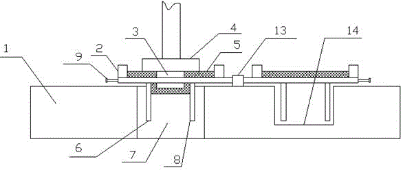
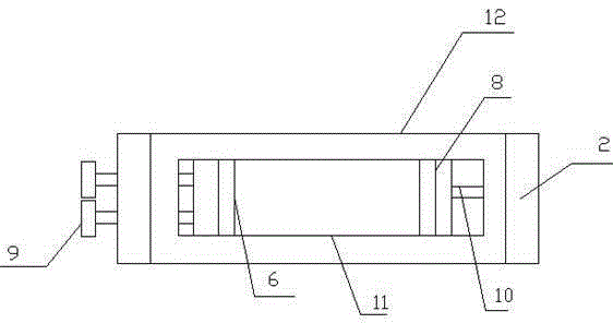
[0016] Such as figure 1 with figure 2 As shown, a high-efficiency stamping die of the present invention includes an upper template 1 and a stamping head assembly arranged at the upper end of the upper template, the stamping head assembly includes a stamping rod, a backing plate 4 and a punch 3, the The backing plate 4 is arranged at the lower end of the stamping rod, and a concave cavity 7 is provided in the middle of the upper template 1 f...


PUM


Abstract

The invention discloses an efficient stamping die. The efficient stamping die comprises an upper die plate and a stamping head assembly arranged at the upper end of the upper die plate. The stamping head assembly comprises a stamping rod, a backing plate and a stamping head. The backing plate is arranged at the lower end of the stamping rod. A cavity is formed in the portion, right facing the stamping head assembly, of the middle of the upper die plate. A receding groove is formed in the portion, located on one side of the cavity, of the upper die plate. A rotating shaft is arranged on the upper end face of the portion between the cavity and the receding groove. Two fixing plates are arranged at the two ends of the rotating shaft respectively. Two pressing blocks are arranged at the upper end of each fixing plate. According to the efficient stamping die, a workpiece is continuously clamped through the fixing plates capable of rotating, and the outer side wall of the workpiece to be stamped is limited through movable baffles and fixed baffles in the stamping process, so that the situation that after the workpiece is stamped, extrusion deformation of the outer side face of the workpiece is caused by the overhigh stamping speed of the stamping head is avoided, the outer wall of the stamped workpiece is more attractive, the upper end face of the workpiece is prevented from cocking, and efficiency is higher.

Description

technical field [0001] The invention relates to a high-efficiency stamping die. Background technique [0002] When the workpiece is being processed, it is necessary to use a stamping die for stamping and deformation to obtain an effective semi-finished product. In the prior art, when the workpiece is stamped, due to the high impact speed of the punch, the protruding part of the stamped workpiece usually has uneven outer walls. situation, or during the stamping process, the fixed parts at both ends of the workpiece will be lifted. This is because the punch is located in the middle of the workpiece. When the punch is pressed down, the two ends of the workpiece will be lifted, although the upper end is fixed , but there will still be slight deformation. And the existing punching method often is to punch a workpiece first, and then clamp after the punching is completed, and this method wastes a lot of time. Contents of the invention [0003] The technical problem to be solve...

Claims


Application Information

Patent Timeline
Patent Type & Authority Applications(China)
IPC IPC(8): B21D37/10B21D43/00
CPCB21D37/10B21D43/00B21D43/003
Inventor 胡云鑫
Owner 东莞市万鑫隆制罐有限公司
Why Eureka
Try Eureka