
A New Scraper Driving Device

A driving device and scraper technology, which is applied in the direction of driving device, metal processing machinery parts, metal processing equipment, etc., can solve the problems of uncontrollable number of revolutions, uncompact structure, complicated installation, etc., and achieve flexible control and design structure. Compact, reliable and smooth transmission

Active Publication Date: 2018-02-02
江苏鼎梁格林嘉能源科技有限公司
View PDF8 Cites 0 Cited by
  • Summary
  • Abstract
  • Description
  • Claims
  • Application Information

AI Technical Summary

Problems solved by technology

[0003] The scraper driving device in the prior art usually mainly includes an ordinary motor, a scraper driving device seat, a coupling, a bearing seat, a scraper gear, a reducer, and a drive shaft. The ordinary motor passes through the coupling Connected with the reducer, the output power of the ordinary motor is transmitted to the reducer, and the reducer transmits the power to the scraper gear through the bearing seat, and the output power and revolutions of the scraper gear are transmitted to the next stage of transmission, while the scraper The gear is a constant number of revolutions, and the number of revolutions is uncontrollable, and the scraper drive device with this structure has many accessories installed, the installation is complicated, and the structure is not compact

Method used


Image

  • A New Scraper Driving Device

Examples


Embodiment Construction

[0012] The following will clearly and completely describe the technical solutions in the embodiments of the present invention with reference to the accompanying drawings in the embodiments of the present invention. Obviously, the described embodiments are only some, not all, embodiments of the present invention. Based on the embodiments of the present invention, all other embodiments obtained by persons of ordinary skill in the art without making creative efforts belong to the protection scope of the present invention.

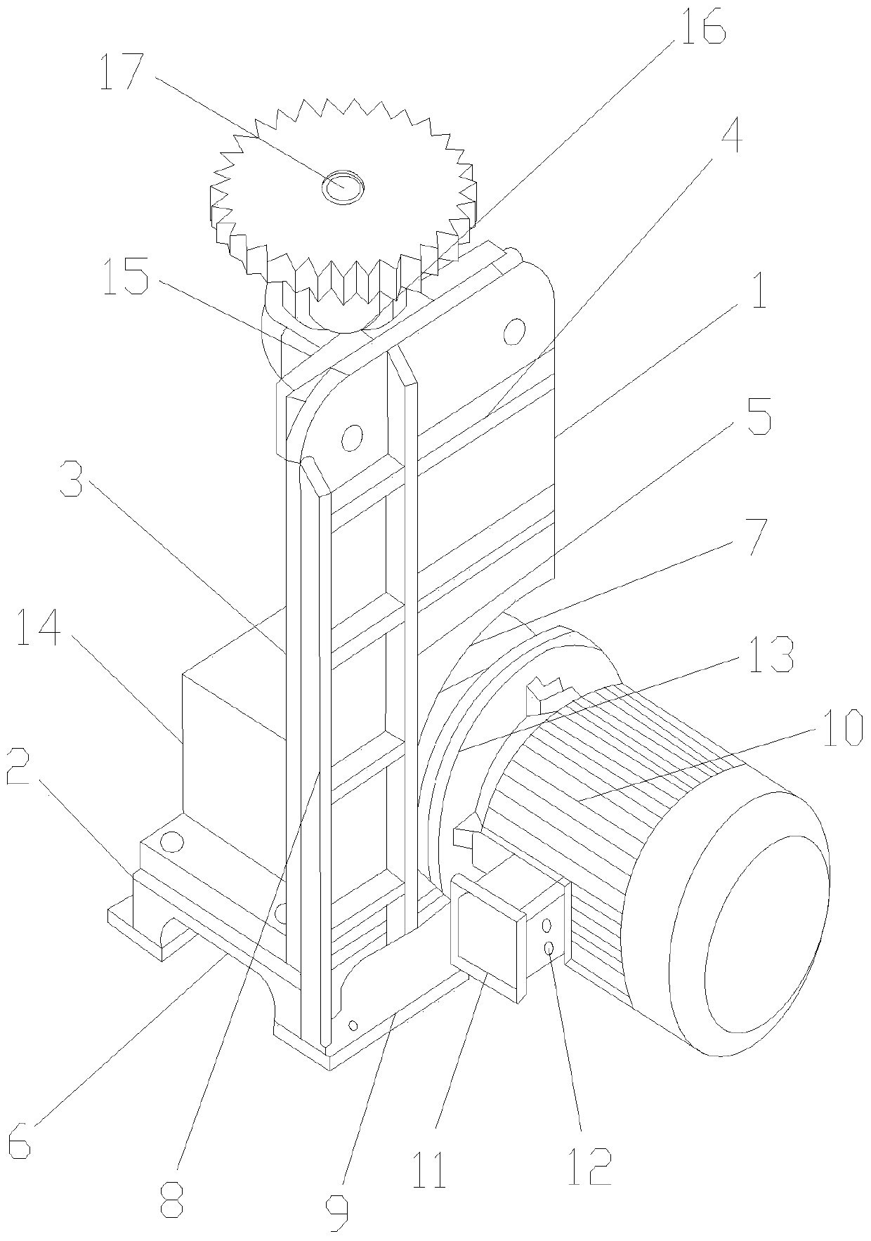
[0013] see figure 1 , a new type of scraper driving device, which includes a scraper driving device seat 1, a scraper driving device seat 1 including a scraper driving device seat base 2 and an end of the scraper driving device seat base 2 The side plate 3 of the scraper driving device seat is located at the bottom end of the side plate 3 of the scraper driving device seat. A variable frequency motor 10 is installed on the variable frequency motor 10. A frequ...


PUM


Abstract

The invention discloses a novel scraping knife driving device. The novel scraping knife driving device comprises a scraping knife driving device holder. The scraping knife driving device holder comprises a scraping knife driving device holder base and a scraping knife driving device holder side plate arranged at one end of the scraping knife driving device holder base. A variable-frequency motor is arranged at the bottom end of one side of the scraping knife driving device holder side plate. A coupling is arranged on the variable-frequency motor. A frequency converter is further arranged on the scraping knife driving device holder base and bonded with the variable-frequency motor through the coupling. A bearing seat is arranged at the top end of the scraping knife driving device holder side plate and connected with the frequency converter through a key groove. A driving shaft is further arranged on the portion, at one side of the bearing seat, of the scraping knife driving device holder side plate. A scraping knife pinion is arranged on the driving shaft. The novel scraping knife driving device has the characteristics that the rotating speed is easy to control, power transmission is reliable and stable, working efficiency is greatly improved, the failure rate is low, the occupied space is small, the number of installed accessories is small, and the structure is compact and simple.

Description

technical field [0001] The invention relates to the technical field of mechanical processing equipment, in particular to a novel scraper driving device. Background technique [0002] With the continuous improvement of the level of science and technology, various scraper knives and scraper drive devices have emerged as the times require. Scraper drive devices are widely used in the field of mechanical processing technology. The performance of scraper knives directly affects the output of labor and The level of machining efficiency. [0003] The scraper driving device in the prior art usually mainly includes an ordinary motor, a scraper driving device seat, a coupling, a bearing seat, a scraper gear, a reducer, and a drive shaft. The ordinary motor passes through the coupling Connected with the reducer, the output power of the ordinary motor is transmitted to the reducer, and the reducer transmits the power to the scraper gear through the bearing seat, and the output power an...

Claims


Application Information

Patent Timeline
Patent Type & Authority Patents(China)
IPC IPC(8): B23Q5/10B23Q5/12
CPCB23Q5/10B23Q5/12Y02P70/10
Inventor 梁念喜徐祖成阮景波张波朱华任兆义王家双吴和福宫文伟肖克龙
Owner 江苏鼎梁格林嘉能源科技有限公司
Learn More