
Gas and solid powder/particle mixture separator

A mixture and solid powder technology, applied in the field of gas and solid mixture separation device, can solve the problems of large one-time investment, complex structure, expensive price, etc., and achieve the effect of large processing flow, wide adaptability and simple structure

Inactive Publication Date: 2008-03-26
陈其林
View PDF0 Cites 2 Cited by
  • Summary
  • Abstract
  • Description
  • Claims
  • Application Information

AI Technical Summary

Problems solved by technology

But its disadvantages are large one-time investment, complex structure, and more steel consumption. Each electric field needs to be equipped with a high-voltage source and control device, which is expensive. When the specific resistance of dust in the flue gas is less than 10 4 Ω·cm or greater than 10 12 Ω·cm, other measures must be adopted to adjust
But its disadvantage is that the discharged muddy sewage must be treated, otherwise it may cause secondary pollution, consume a certain amount of water, cannot be used for hydraulic powder such as cement, and useful dust is difficult to recycle.

Method used


Image

  • Gas and solid powder/particle mixture separator
  • Gas and solid powder/particle mixture separator
  • Gas and solid powder/particle mixture separator

Examples


Embodiment 1

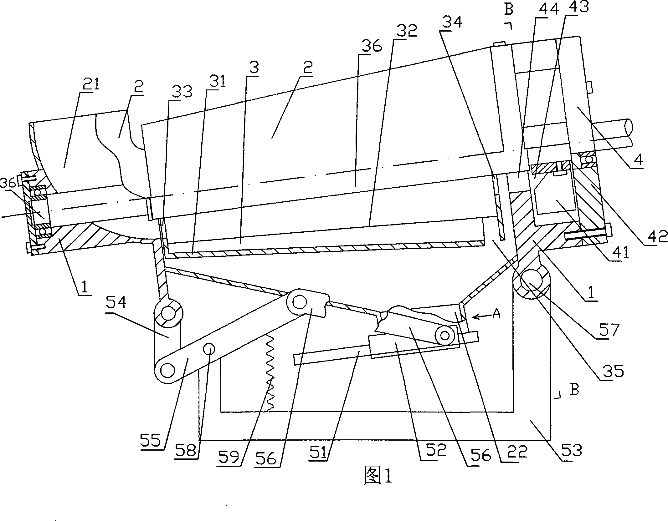
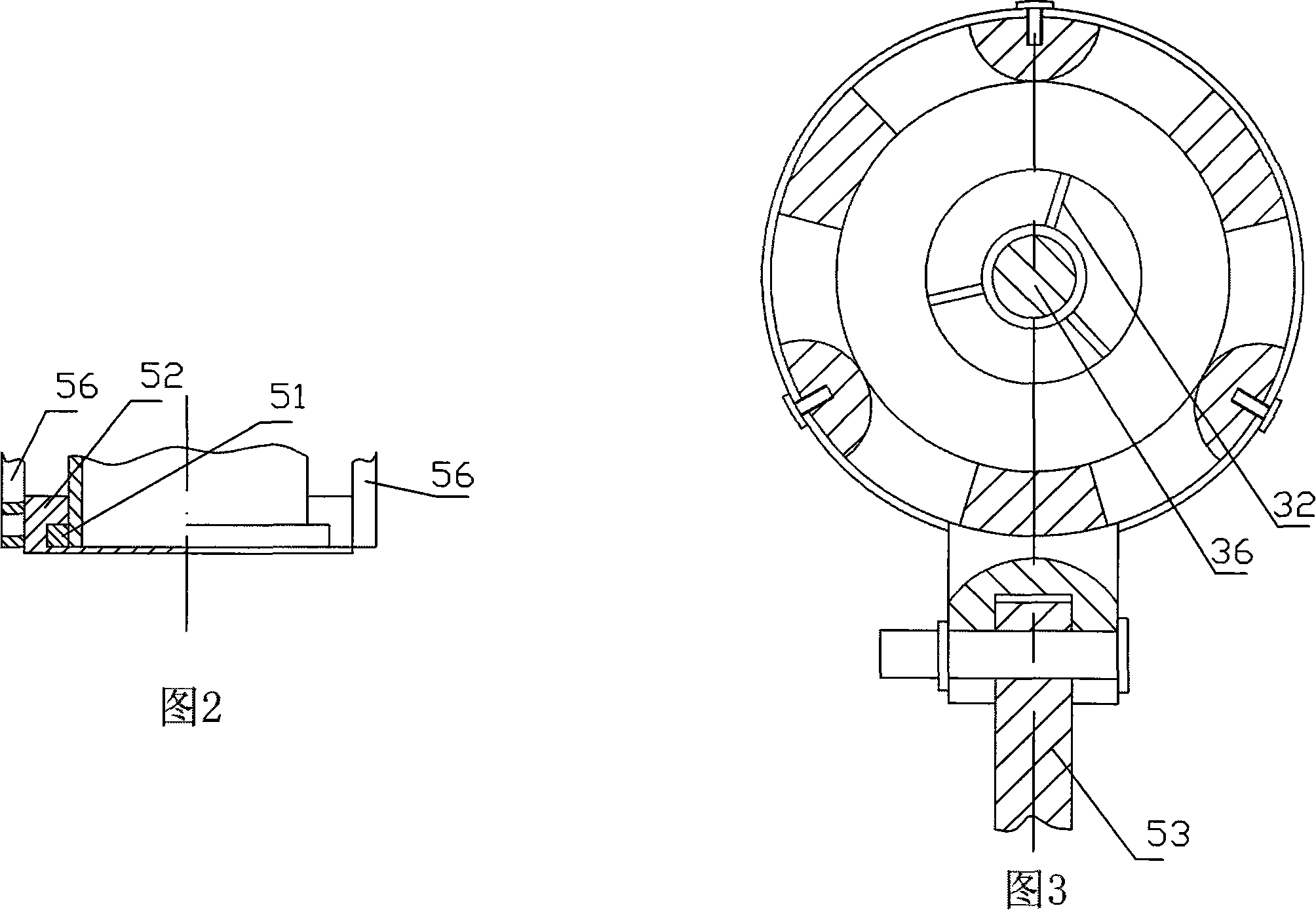
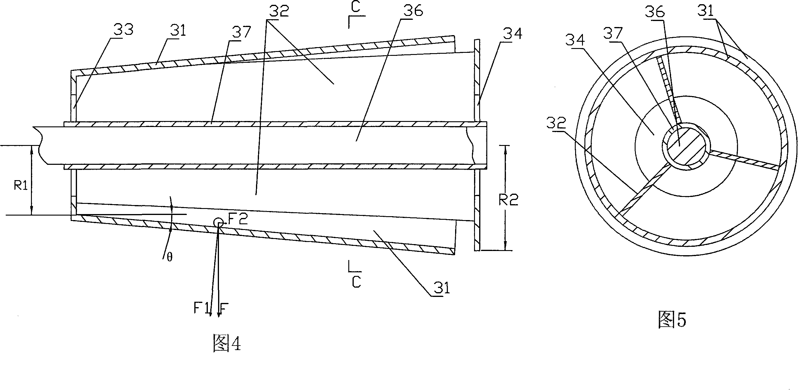
[0026] As shown in accompanying drawings 1-5: the gas and solid powder mixture separator, which includes a frame 1, a casing 2, a mixture separation rotor 3, a fan 4 and a powder mixture discharge device; the casing 2 is installed on the top of the frame 1, A feed port 21 is provided on it, and a discharge port 22 is provided at the bottom of the shell; the mixture separation rotor 3 includes a rotor shell 31, three or more partitions 32 and a sleeve 37, and the inner cavity of the shell 31 is a circle Frustum shape, the radius R1 on the left side of the frustum-shaped cavity is less than (or equal to) the radius R2 on the right side, the sleeve 37 is fixedly installed in the frustum-shaped inner cavity of the shell 31 through the partition plate 32, and the central axis of the sleeve 37 is located in the shell On the central axis of the truncated conical cavity of 31, the partition 32 divides the cavity between the shell 31 and the sleeve 37 into three or more isolated cavitie...

Embodiment 2

[0030]As shown in accompanying drawing 6: gas and solid powder particle mixture separator, it comprises frame 1, shell 2, mixture separation rotor 3, blower fan 4 and powder particle mixture discharge device; Powder particle mixture discharge device comprises valve and sliding mechanism; The sliding mechanism includes a T-shaped lever 60, a connecting rod 61 and a valve sleeve 62. The T-shaped lever 60 is movably installed on the discharge port 22 of the casing 2 through a rotating shaft 63. The T-shaped lever 60 can swing along the rotating shaft 63. The left branch of the T-shaped lever 60 A counterweight 64 is installed at the end, and a slot 65 is opened at the lower branch end of the T-shaped lever 60. The valve sleeve 62 is movably installed on the discharge port 22 of the casing 2, and it is also moved through the connecting rod 61 and the right branch end of the T-shaped lever 60. connected, the valve sleeve 62 can slide up and down along the discharge port; the valve i...


PUM


Abstract

The present invention relates to a gas and solid powder mixture separator. Said separator includes the following several portions: machine frame, external shell, mixture separation rotor, blower fan and powder granules discharge devices. Said invention also provides the concrete structure of above-mentioned every portion, and also provides the working principle of said gas and solid powder separator and its concrete operation method.

Description

technical field [0001] The invention relates to a gas and solid mixture separation device, in particular to a gas and solid powder mixture separator. Background technique [0002] At present, the separation methods of gas and solid powder mixture are generally divided into two categories: wet separation method and dry separation method. Dry separation methods are divided into filtration method, cyclone method and electrostatic method. [0003] The filtration separation method has high separation efficiency, can meet strict environmental protection requirements, has stable operation and strong adaptability. However, its disadvantages are large volume, high cost, complicated operation and maintenance, and many auxiliary equipment. Generally, it is used below 270 ° C. The filter material can generally be used for 2 to 3 years. Material selection and production are difficult. [0004] Because there are no moving parts, the cyclone separation method has the advantages of conve...

Claims


Application Information

Patent Timeline
Patent Type & Authority Applications(China)
IPC IPC(8): B04B1/04B04B7/12B04B7/02B04B11/04
Inventor 陈其林
Owner 陈其林
Learn More