
Tractor for elevator

A traction machine and elevator technology, applied in the field of elevator traction machines, can solve the problems of hindering cranking operation, hindering operation, hindering the mechanical connection between encoder and rotating parts of the traction machine, etc., and achieves the effect of convenient layout and operation

Inactive Publication Date: 2016-01-27
SHANGHAI MITSUBISHI ELEVATOR CO LTD
View PDF7 Cites 5 Cited by
  • Summary
  • Abstract
  • Description
  • Claims
  • Application Information

AI Technical Summary

Problems solved by technology

[0005] First, when the elevator is installed, it is necessary to wind the ropes driving the elevator on the sheave, and the ropes of the installed and running elevators need to be replaced regularly. The position between the guide rails hinders the operation of the job
[0006] Second, in case of an emergency situation in the elevator, when it is necessary to use the manual cranking device and manpower to turn the rotating parts of the traction machine to rescue the passengers in the elevator, since the rotating parts of the traction machine are located between the stator shell and the The position between the guide rails hinders the operation of the barring
Because the rotating parts of this kind of traction machine are all located between the stator shell and the guide rail, and the traction machine is provided with a connecting short shaft at the hollow shaft in the middle, which hinders the mechanical connection between the encoder and the rotating parts of the traction machine. The arrangement and operation of the encoder is very inconvenient

Method used


Image

  • Tractor for elevator
  • Tractor for elevator
  • Tractor for elevator

Examples


Embodiment Construction

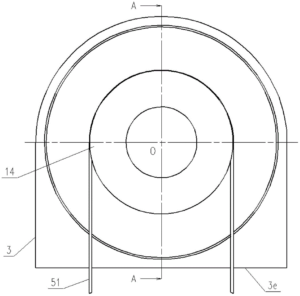
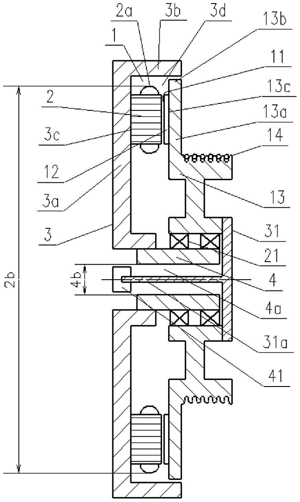
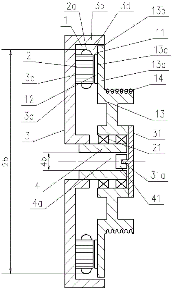
[0043] Such as figure 1 and figure 2 Shown is the first embodiment of the elevator traction machine of the present invention, including a motor 1, a fixed frame 3, a fixed main shaft 4, a rotor case 13, a sheave 14 for driving an elevator rope 51, a bearing 21, a rotating body 31, an encoding device 41;

[0044] The motor 1 comprises a stator 2 and a rotor 12 provided with a stator coil 2a, and the stator 2 and the rotor 12 are relatively arranged; the motor 1 is a disc motor, which provides rotational power for the sheave 14 driving the elevator rope 51;

[0045] The fixed base 3 has a hollow disc-shaped extension 3a extending radially outward, and a stator installation part 3c provided on the extension 3a; the stator 2 is fixedly arranged at the stator installation part 3c;

[0046] The fixed main shaft 4 and the fixed machine base 3 are split structures, the fixed main shaft 4 is fixedly connected to the fixed machine base 3, and the fixed main shaft 4 supports the rotat...


PUM


Abstract

The present invention discloses a tractor for an elevator. The tractor comprises a motor, a fixed machine base, a fixed main shaft, a rotor case, a rope wheel for driving ropes of the elevator, a bearing, a rotating body and an encoder, wherein a stator installation part is disposed at a hollow disc-type extension part of the fixed machine base, a rotor installation part is disposed at a hollow disc-type extension part of the rotor case and is opposed to the stator installation part, the diameter of a hollow part of the fixed main shaft is larger than that of a rotating shaft part of the rotating body, the rotating body rotates along with the rotor case, and the encoder is disposed at the rotating shaft part of the rotating body. A novel structure is provided for the elevator tractor using a disc-type electric motor, the tractor is fully utilized to fix space of the hollow part of a main shaft, arrangement and operation of the encoder become convenient, overall thinness of the tractor is maintained, and the tractor is suitable for elevators, with small machine rooms or without machine rooms, requiring thinness of the tractor.

Description

technical field [0001] The invention relates to an elevator driving device, in particular to an elevator traction machine. Background technique [0002] The overall dimensions and installation method of the elevator traction machine have a great influence on the required installation space. In order to save installation space, traction machines for thin elevators are being used more and more. [0003] A kind of elevator machinery disclosed in Chinese invention patent ZL94193214.1 is a traditional thin-shaped elevator traction machine. The structural features of the traction machine are: using a disc motor; using a flat machine structure; through the lugs protruding from the stator shell on the opposite sides of the stator shell along the direction of the guide rail, and the hollow center of the traction machine The connecting short shaft at the shaft installs and fixes the traction machine on the guide rail. This kind of traction machine is thinner, which is beneficial to...

Claims


Application Information

Patent Timeline
Patent Type & Authority Applications(China)
IPC IPC(8): B66B11/04
Inventor 李伟方凯
Owner SHANGHAI MITSUBISHI ELEVATOR CO LTD
Learn More