

Unlocking apparatus
A technology for unlocking devices and reading devices, which is applied in the field of unlocking devices, can solve the problems of poor convenience and time-consuming, and achieve the effect of reducing convenience and simple structure
- Summary
- Abstract
- Description
- Claims
- Application Information
AI Technical Summary
Problems solved by technology
Method used
Image

Examples
Embodiment approach 1
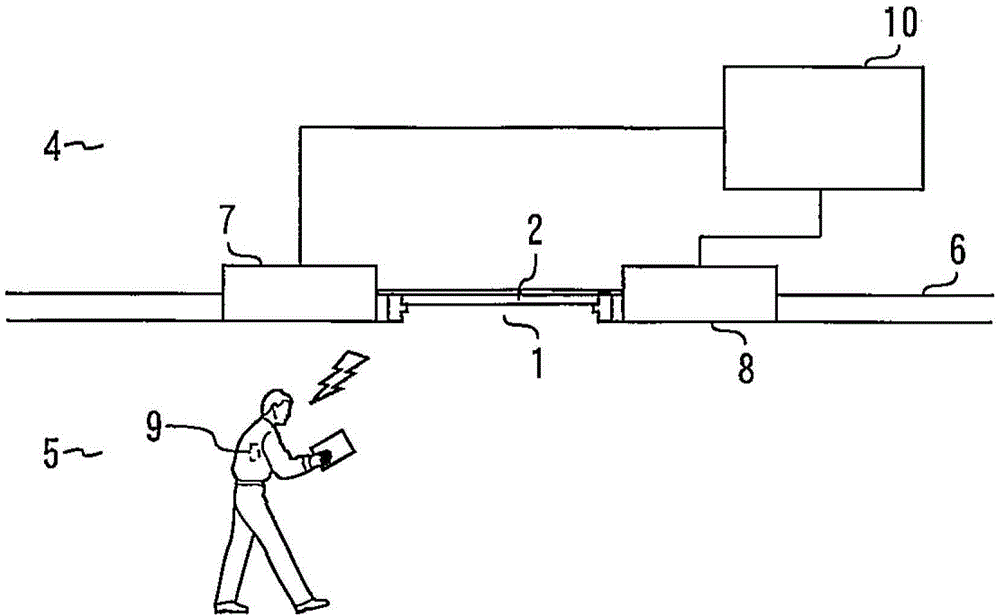
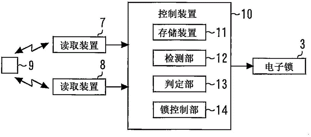
[0026] figure 1 It is a figure which shows the example of the unlocking device in Embodiment 1 to which this invention was applied. figure 2 It is a figure which shows the structure of the unlocking device in Embodiment 1 of this invention.
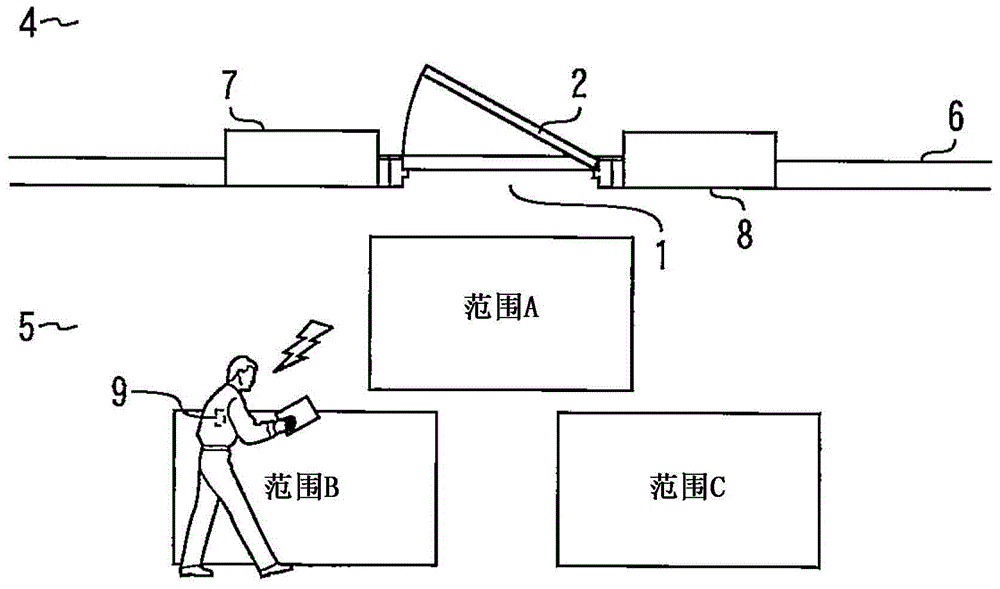
[0027] In a building having this unlocking device, a door 2 is provided at an entrance 1 through which only authorized persons are intended to pass. The door 2 is locked by means of an electronic lock 3 . In this embodiment, an example in which access to the room 4 is restricted is shown. That is, the door 2 divides the room 4 and the corridor 5 .
[0028] The place where the unlocking device is applied is not limited thereto. For example, the unlocking device can also be applied to a door provided at an entrance of a building. For example, the present unlocking device can also be applied to doors provided for exits from building sites.
[0029] A reading device 7 and a reading device 8 are provided on a wall 6 adjacent to the door...
Embodiment approach 2
[0067] Figure 6 It is a figure which shows the example of the unlocking device in Embodiment 2 to which this invention was applied. The structure of the unlocking device in this embodiment corresponds to a structure obtained by adding a sensor 15 to the structure disclosed in the first embodiment.
[0068] The sensor 15 detects the presence of a person in the vicinity of the door 2 . For example, the sensor 15 detects the presence of a person within a range in which the detection unit 12 can detect the presence of the tag 9 . For example, the sensor 15 detects the presence of a person over the entire range in which the reading device 7 and the reading device 8 can receive identification information from the tag 9 . The sensor 15 may detect the presence of a person in a part of the range where the reading device 7 and the reading device 8 can receive identification information from the tag 9 . The sensor 15 also detects the presence of a person not holding the tag 9 . The ...
Embodiment approach 3
[0072] Figure 8 It is a figure which shows the example of the unlocking device in Embodiment 3 to which this invention was applied. Figure 9 It is a figure which shows the structure of the unlocking device in Embodiment 3 of this invention. The configuration of the unlocking device in this embodiment corresponds to a configuration obtained by adding a detection unit 16 to the control device 10 disclosed in the second embodiment.
[0073] The detection unit 16 detects that a person has moved not to approach the door 2 based on the result detected by the sensor 15 . For example, consider a case where, as the sensor 15 , sensors 15 a to 15 e that can detect the temperature of a person are arranged along the passage direction of the corridor 5 . The direction of travel for corridor 5 is Figure 8 The D direction shown or the opposite direction of the D direction. When the sensors 15a to 15e detect the presence of a person, they transmit information indicating that to the con...
PUM
 Abstract
Description
Claims
Application Information