

Fluorescent baking machine drying shaft
A baking machine and fluorescent lamp technology, applied in the field of baking machine components, can solve the problems of accidental breakage of the shaft head, loss of heat energy, affecting normal production, etc., and achieve the effects of avoiding accidental breakage, easy use, and reducing accidental losses.
Inactive Publication Date: 2016-01-27
湖北如日电气股份有限公司
View PDF0 Cites 0 Cited by
- Summary
- Abstract
- Description
- Claims
- Application Information
AI Technical Summary
Problems solved by technology
[0002] In the process of producing fluorescent lamps, a baking machine is used to bake the tube body. The traditional equipment uses a stainless steel rotating shaft to bake in rotation. However, since stainless steel is a metal heat-conducting material, the equipment will be baked during the baking process. The internal heat transfers to the outside and causes heat loss. In recent years, equipment manufacturers have used ceramic shafts for metal shafts to avoid heat loss. The use of such ceramic shafts greatly reduces heat loss, but in In actual use, the shaft head at the transmission end of the ceramic shaft is very easy to cause accidental breakage during uninterrupted rotation, which directly affects the normal production
Method used
View moreImage
Smart ImageViewing Examples

Examples
Embodiment Construction
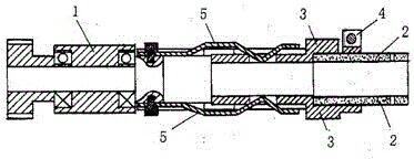
[0010] figure 1 As shown: the outer end of the shaft rod 1 of the drying shaft is connected and fixed with the ceramic shaft 2 through the metal sleeve 3 . The metal sleeve 3 is provided with a screw clip 4 for fastening the ceramic shaft 2 . There is a fastening clip 5 between the shaft rod 1 and the ceramic shaft 2 .
Login to View More PUM
 Abstract
The present invention provides a fluorescent baking machine drying shaft. The shaft rod outer end head of the drying shaft and a ceramic shaft are connected and fixed through a metal sleeve. The metal sleeve is provided with a screw clamp which fastens a ceramic shaft, and a fastening card is arranged between a shaft rod and the ceramic shaft. Through connecting the shaft rod and the ceramic shaft by the metal sleeve, the characteristic of reducing thermal energy loss of the ceramic shaft is maintained, and the phenomenon of a loss caused by accidental breakage can be avoided through the metal sleeve.
Description
technical field [0001] The invention relates to a roasting machine component used in producing fluorescent lamps, in particular to a drying shaft of a fluorescent lamp roasting machine. Background technique [0002] In the process of producing fluorescent lamps, a baking machine is used to bake the tube body. The traditional equipment uses a stainless steel rotating shaft to bake in rotation, but since stainless steel is a metal heat-conducting material, the equipment will be baked during the baking process. The internal heat transfers to the outside and causes heat loss. In the equipment transformation in recent years, equipment manufacturers use ceramic shafts for metal shafts to avoid heat loss. The use of such ceramic shafts greatly reduces heat loss, but in In actual use, the shaft head at the transmission end of the ceramic shaft is very easy to cause accidental breakage during uninterrupted rotation, which directly affects the normal production. Contents of the inve...
Claims
Login to View More Application Information
Patent Timeline
 Patent Type & AuthorityApplications(China)
IPC IPC(8): H01J9/24
Inventor张静霞张小二
Owner湖北如日电气股份有限公司