A flexible multi-joint surgical microinstrument for robot-assisted minimally invasive surgery

A robot-assisted, minimally invasive surgery technology, used in surgical robots, surgical forceps, etc., to achieve the effects of convenient positioning, improved working range and flexibility, and flexible operation

Active Publication Date: 2017-10-27
吉林省金博弘智能科技有限责任公司
View PDF1 Cites 0 Cited by
  • Summary
  • Abstract
  • Description
  • Claims
  • Application Information

AI Technical Summary

Problems solved by technology

[0003] In order to solve the problem that the existing minimally invasive surgical robotic surgical microinstruments cannot be positioned and moved in the patient's body (that is, adjust the position and posture) by the surgical microinstruments themselves, the present invention further provides a flexible robot-assisted minimally invasive surgical instrument. Micro-instruments for polyarticular surgery

Method used


Image

  • A flexible multi-joint surgical microinstrument for robot-assisted minimally invasive surgery
  • A flexible multi-joint surgical microinstrument for robot-assisted minimally invasive surgery
  • A flexible multi-joint surgical microinstrument for robot-assisted minimally invasive surgery

Examples


specific Embodiment approach 1

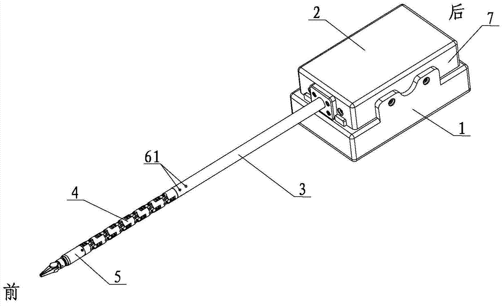
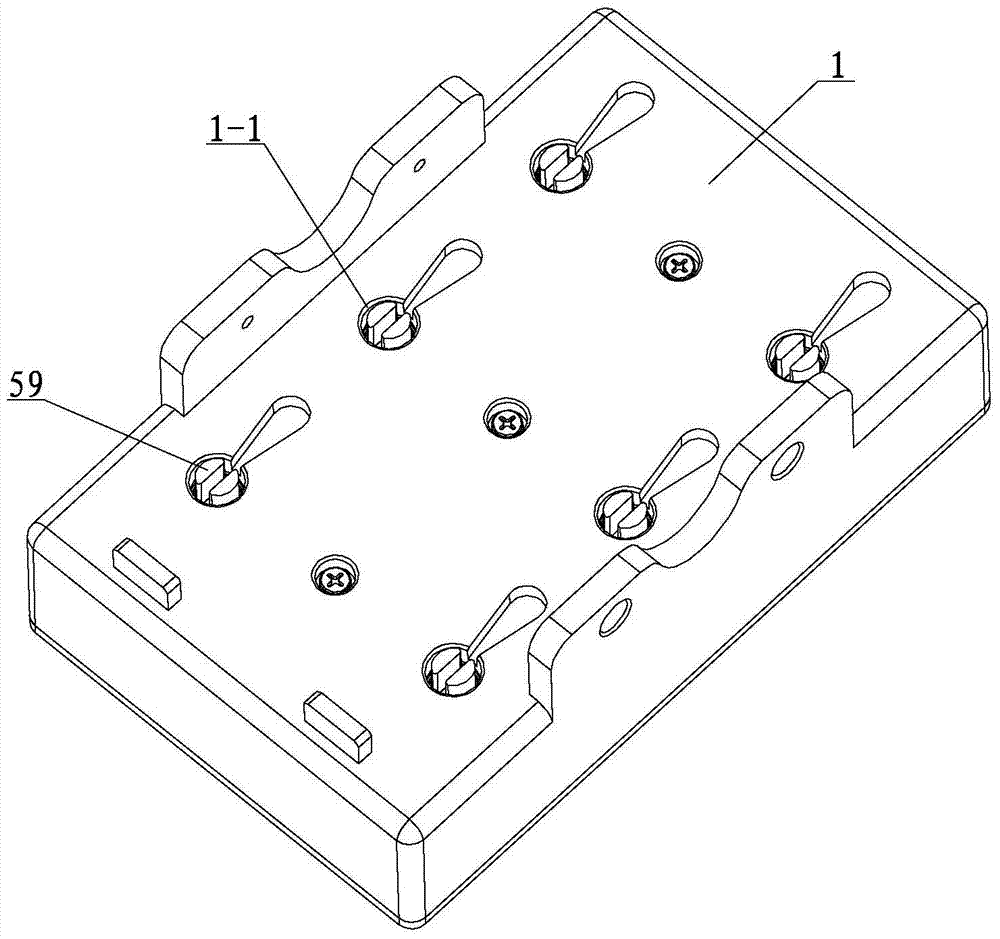
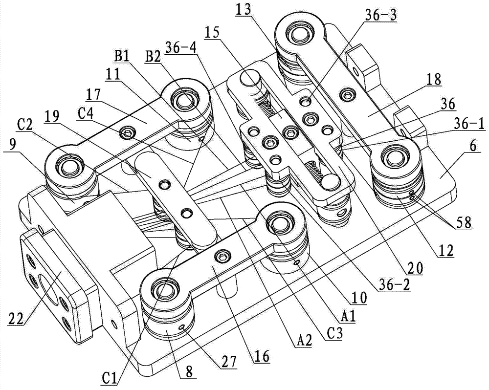
[0025] Specific implementation mode one: combine Figure 1 to Figure 11 Explain that this embodiment includes a drive box 1, a transmission mechanism 2, a catheter 3, a flexible bending arm mechanism 4, a forceps mechanism 5, six transmission parts 59 and six miniature drive motors, and the transmission mechanism 2 includes a bottom plate 6, an upper cover 7, First bending transmission mechanism 8, second bending transmission mechanism 9, third bending transmission mechanism 10, fourth bending transmission mechanism 11, surgical forceps opening and closing transmission mechanism 12, surgical forceps rotation transmission mechanism 13, two bending guide mechanisms 14, The decoupling mechanism 15, the first top plate 16, the second top plate 17, the third top plate 18, the fourth top plate 19, the fifth top plate 20, the conduit fixing part 21 and the conduit baffle plate 22, the upper and lower end surfaces of the bottom plate 6 are provided with the first installation Hole 6-1...

specific Embodiment approach 2

[0026] Specific implementation mode two: combination image 3 and Figure 5 Describe this embodiment, the first bending transmission mechanism 8 of this embodiment, the second bending transmission mechanism 9, the third bending transmission mechanism 10 and the fourth bending transmission mechanism 11 are all composed of a bending transmission shaft 23, a bending transmission wheel 24, a bending transmission The upper bearing 25, the lower bearing 26 of the bending transmission and two first set screws 27 are composed. The bending transmission shaft 23 is a stepped shaft. -2. The third section 23-3 of the curved transmission shaft and the fourth section 23-4 of the curved transmission shaft, wherein the front and rear sides of the section 23-1 of the curved transmission shaft are respectively provided with square flats, and the inner ring of the lower bearing 26 of the curved transmission is installed on the curved On the outer wall of the second section 23-2 of the transmiss...

specific Embodiment approach 3

[0027] Specific implementation mode three: combination Figure 6 Describe this embodiment, the surgical forceps opening and closing transmission mechanism 12 and the surgical forceps rotation transmission mechanism 13 of this embodiment are all composed of a terminal drive shaft 28, an end drive upper bearing 30, a terminal drive lower bearing 31, two terminal drive wheels 29 and four A second set screw 58 is formed, and a second annular wire groove (29-1) is provided on the outer surfaces of the two end drive wheels (29), and the two second annular wire grooves (29-1) are provided on the outer surfaces of the two end drive wheels (29). 1) Parallel to each other, between the two second annular steel wire grooves 29-1 is a wide transmission wheel 29-3, the upper and lower ends of the two second annular steel wire grooves 29-1 are narrow transmission wheels 29-2, and the wide transmission wheel 29- 3 A second concave hole 29-4 is provided near the edge of the second annular wire...


PUM


Abstract

A flexible multi-joint surgical micro-instrument for robot-assisted minimally invasive surgery, in order to solve the problem that the existing minimally invasive surgical robot surgery micro-instrument cannot be positioned, moved and other operations in the patient's body relying on the surgical micro-instrument itself. The transmission mechanism is installed on the drive box, and the six connection holes correspond to the first installation hole, the second installation hole, the third installation hole, the fourth installation hole, the fifth installation hole and the sixth installation hole respectively. A transmission part is installed in the hole, and the first bending transmission mechanism, the second bending transmission mechanism, the third bending transmission mechanism, the fourth bending transmission mechanism, the surgical forceps opening and closing transmission mechanism and the surgical forceps rotation transmission mechanism are respectively connected with the corresponding transmission parts , the lower end of each transmission part is connected with the micro-drive motor, the rear end of the catheter is connected with the catheter fixing part, the front end of the catheter is connected with the flexible bending arm mechanism, and the front end of the flexible bending arm mechanism is connected with the surgical forceps mechanism. The invention is used for abdominal surgery.

Description

technical field [0001] The invention relates to a surgical instrument for minimally invasive surgery, in particular to a flexible multi-joint surgical microinstrument for robot-assisted minimally invasive surgery. Background technique [0002] Minimally invasive surgery has the advantages of less bleeding, quick recovery, and low risk of wound infection, and has been recognized in clinical applications. The introduction of minimally invasive surgical robot systems makes surgical operations more precise and stable on this basis. The end effector for minimally invasive surgery is a key instrument in minimally invasive surgery. The invention patent with the Chinese patent number 201310414968.4 and the publication date of December 11, 2013 discloses a micro-instrument for minimally invasive surgical robotic surgery. Due to the design of the patent The flexible wrist mechanism 4 enables this patent to complete the swing and pitch movements of the wrist; however, the guide rod 3 o...

Claims


Application Information

Patent Timeline
Patent Type & Authority Patents(China)
IPC IPC(8): A61B34/30A61B17/29
Inventor 冯美金星泽赵继付宜利董光友
Owner 吉林省金博弘智能科技有限责任公司
Why Eureka
Try Eureka