Gas purifier

A gas purifier, a technology for purifying gas, applied in chemical instruments and methods, separation methods, transportation and packaging, etc., can solve the problems of filter cotton or activated carbon pore blockage, affecting filtration performance, etc., to improve filtration effect and improve the effect. Effect

Active Publication Date: 2016-02-03
邹岳明
9 Cites 4 Cited by

AI-Extracted Technical Summary

Problems solved by technology

[0002] Gas purifiers in the prior art generally use filter cotton or activated carbon for multiple layers of filtration to adsorb particulate matter and harmful components in the gas. However, a...

Abstract

The invention relates to a gas purifier which can purify air and prevent blockage caused by particles or impurities. The gas purifier comprises a closed housing, wherein a hollow shaft is in running fit with the interior of the housing, and a plurality of filter cylinders with the left ends closed and openings in the right ends fixedly sleeve the hollow shaft; a plurality of spout holes are formed in the wall of the hollow shaft, and one end part of the hollow shaft is used for water intake, so that all the spout holes can spray water to the inner walls of the filter cylinders; the hollow shaft is in transmission fit with a transmission mechanism to enable the filter cylinders to rotate; the opening part of each filter cylinder and the inner wall of the housing are in rotary sealing fit through a sealing mechanism; a gas inlet used for inputting a gas to be purified is formed in the wall of the housing and located at the left side of the sealing mechanism in sealing fit with the filter cylinder on the leftmost side, and a gas outlet is formed in the wall of the housing and located at the right side of the sealing mechanism in sealing fit with the filter cylinder on the rightmost side.

Application Domain

Combination devicesDispersed particle filtration +1

Technology Topic

EngineeringMechanical engineering +1

Image

  • Gas purifier
  • Gas purifier

Examples

  • Experimental program(1)

Example Embodiment

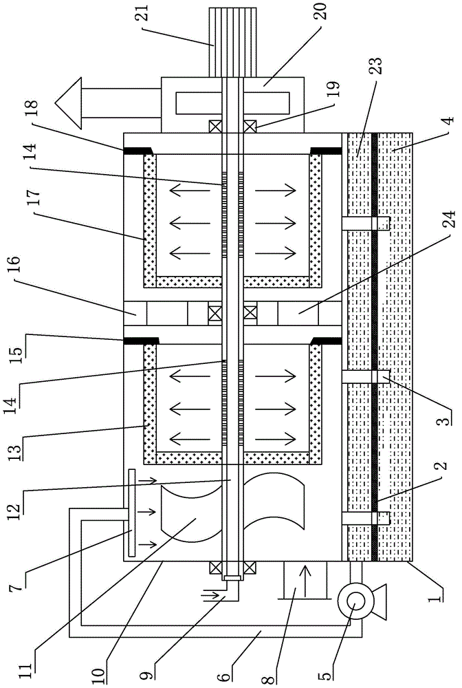
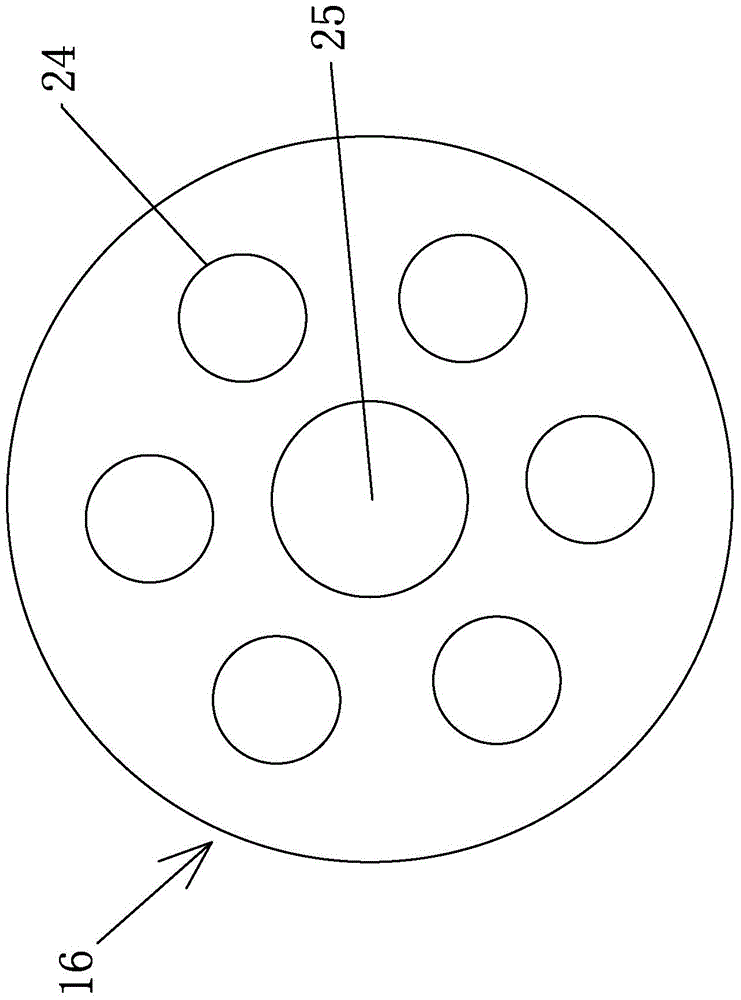
[0014] like figure 1 As shown, the gas purifier of the present invention includes: a water storage tank 1, a filter layer 2, a return pipe 3, a sewage layer 4, a water pump 5, a water pipe 6, a shower 7, an air inlet pipe 8, an water inlet pipe 9, a housing 10, Rotary filter screen 11, hollow shaft 12, filter cartridge 13, spray hole 14, sealing mechanism 15, bracket 16, filter cartridge 2 17, sealing mechanism 2 18, bearing 19, induced draft fan 20, motor 21, water purification Layer 23, wind hole 24, shaft hole 25.
[0015] In the water storage tank 1, from top to bottom, there are respectively a water purification layer 23, a filter layer 2 for filtering particulate matter, and a sewage layer 4, and the bottom of each return pipe 3 is connected to the sewage layer; The connected water outlet is connected to the sprinkler 7 through the water pump 5; a cylindrical shell 10 is arranged above the water storage tank 1, and the hollow shaft 12 is horizontally fitted in the shell 10 through a plurality of bearings 19, adjacent to the hollow shaft The left end of 12 is fixedly connected with a plurality of rotating filter screen sheets 11 that are symmetrically distributed in the center, and the rotating filter screen sheet 11 is provided with a plurality of mesh holes (the number and diameter of the mesh holes are determined according to the size of the droplets that need to be generated. Select), the right side of the rotating filter screen 11 is provided with a filter cartridge 13 fixed on the hollow shaft 12, the filter cartridge 13 is a cylindrical thin-walled hollow structure without a right end surface and the material is filter cotton containing activated carbon or The whole is made of activated carbon or ultrafiltration membrane (the pore diameter of each filter cartridge is selected according to the requirements of filtering air, at least PM2.5 particles can be filtered), and the hollow shaft located in filter cartridge 1 is equipped with A plurality of water spray holes 14 communicated with the internal through holes of the hollow tube. A sealing mechanism 15 (generally a sealing ring) is provided between the right end of the filter cartridge 13 and the housing 10. The right side of the filter cartridge 13 Adjacent is provided with the support 16 that is fixed on the casing 10, as figure 2 As shown, the bracket 16 is in the shape of a disc, and a plurality of air passage holes 24 are arranged circumferentially on the outer end of the bracket, and the shaft hole 25 in the center of the bracket 16 is matched with the hollow shaft 12 bearing.
[0016] The right side of this support 16 is provided with a filter cartridge two 17 (preferably pore diameter is smaller than filter cartridge one 13) with the same structure as filter cartridge one 13. The water spray hole 14 connected with the internal through hole, the sealing mechanism 18 is provided between the right end of the filter cartridge 2 and the housing 10, the right end of the housing 10 is provided with an induced draft fan 20, and the right end of the hollow shaft 12 is installed in the induced Inside the blower fan 20 , a motor 21 for driving the hollow shaft 12 to rotate is provided on the right side of the induced draft fan 20 .
[0017] The left side of the water storage tank 1 is provided with a water pump 5, which takes water from the top of the filter layer 2 in the water storage tank 1, and the water pump 5 is connected with the sprinkler 7 through the water pipe 6; the water inlet pipe 9 is connected to the hollow shaft through a rotating sealing connection device The left end of the left end rotates and is connected with the inner through hole of the hollow shaft 12, and the water inlet pipe 9 is connected with a high-pressure water source, or takes water from the water storage tank 1 through the water pump 5;
[0018] The working process of the gas purifier includes: the motor 21 drives the induced draft fan 20 to work, and the water pump 5 works at the same time. After entering the housing 10, the larger particles or oil stains are combined with the mist liquid and flow to the cover plate 23, the gas passes through the filter cartridge 1 and the filter cartridge 2 in turn, and the smaller particles and impurities in the gas are filtered by the above-mentioned The cylinder absorbs, and finally the gas is discharged from the air outlet 22; the clean water entering from the water inlet pipe 9 is sprayed out through the water spray hole 14 (the water spray method is regular (for example, every 1-3 minutes, spray water for 10-30 seconds) or always Spray water), wash the inner wall of the filter cartridge 13 and the filter cartridge 2 17, rotate the filter cartridge, make the water pass through the wall of the filter cartridge under the action of centrifugal force, and the particles adsorbed on the outer wall of the filter cartridge, Oil and other impurities are washed, so that the micropores on filter cartridge 1 and filter cartridge 2 are not blocked and the filtering capacity is not attenuated.
[0019] Apparently, the above-mentioned embodiments are only examples for clearly illustrating the present invention, rather than limiting the implementation of the present invention. For those of ordinary skill in the art, on the basis of the above description, other changes or changes in different forms can also be made. It is not necessary and impossible to exhaustively list all the implementation manners here. And these obvious changes or modifications derived from the spirit of the present invention are still within the protection scope of the present invention.

PUM

no PUM

Description & Claims & Application Information

We can also present the details of the Description, Claims and Application information to help users get a comprehensive understanding of the technical details of the patent, such as background art, summary of invention, brief description of drawings, description of embodiments, and other original content. On the other hand, users can also determine the specific scope of protection of the technology through the list of claims; as well as understand the changes in the life cycle of the technology with the presentation of the patent timeline. Login to view more.

Similar technology patents

Electrolytic copper foil drying device

Owner:GUANGDONG FINE YUAN SCI TECH CO LTD

Material pulverizing and sieving device

Owner:CHENZHOU JINTONG INFORMATION TECH CO LTD

Solid-liquid mixing and stirring device and stirring method

Owner:江苏易金达新材料科技有限公司

Equipment and method for mapping variable sub carriers

InactiveCN1917418AImprove the effectImprove the probability of HARQ transmission failure
Owner:BEIJING SAMSUNG TELECOM R&D CENT +1

Classification and recommendation of technical efficacy words

  • Improve the effect
  • Improve filtering effect

Liquid blast furnace slag granulation method and device thereof

InactiveCN101665845AIncrease impactImprove the effect
Owner:TSINGHUA UNIV +1

Real-time subtitle display method and system

ActiveCN106331893Aimprove intelligibilityImprove the effect
Owner:IFLYTEK CO LTD

Calculation method for electric quantities of battery, device and terminal

InactiveCN102508172AImproved power calculation accuracyImprove the effect
Owner:ZTE CORP

Information reminding method and device

ActiveCN104618218AImprove the effect
Owner:GUANGZHOU KUGOU TECH

Gas filter device

InactiveCN102059031AImprove filtering effectImprove filtration capacity
Owner:赵艳萍

Air filter for engine

Owner:WUHU AOBENMA AUTOMOBILE PARTS
Why Eureka
Try Eureka