Supercharge Your Innovation With Domain-Expert AI Agents!

Wafer-Level Encapsulation Die Design

A mold and molding technology, used in household appliances, other household appliances, household components, etc., can solve problems such as inability to use transfer molding, uneven distribution of molding compounds, etc.

Active Publication Date: 2018-01-26
TAIWAN SEMICON MFG CO LTD
View PDF5 Cites 1 Cited by
  • Summary
  • Abstract
  • Description
  • Claims
  • Application Information

AI Technical Summary

Problems solved by technology

However, transfer molding cannot be used on packages including circular wafers due to the uneven distribution of the molding compound

Method used


Image

  • Wafer-Level Encapsulation Die Design
  • Wafer-Level Encapsulation Die Design
  • Wafer-Level Encapsulation Die Design

Examples


Embodiment Construction

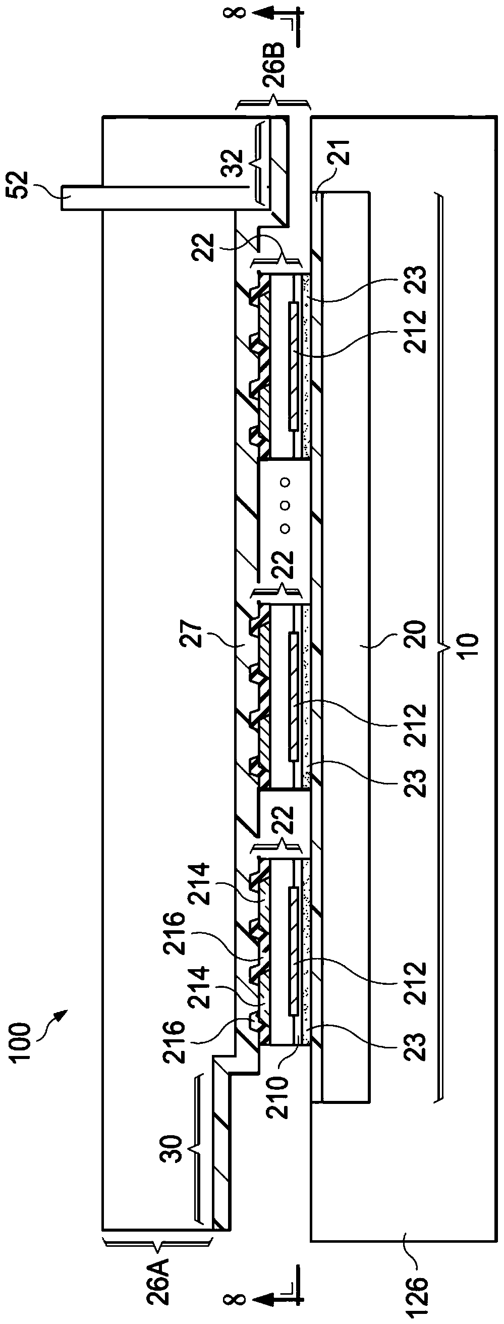
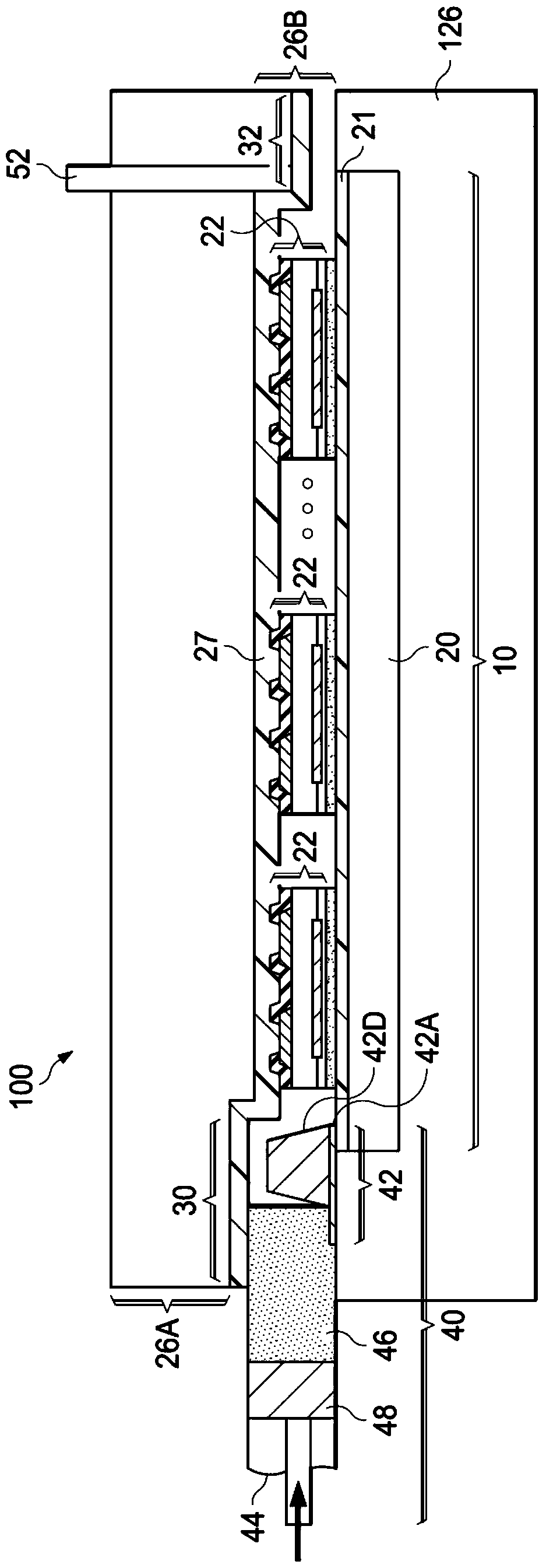
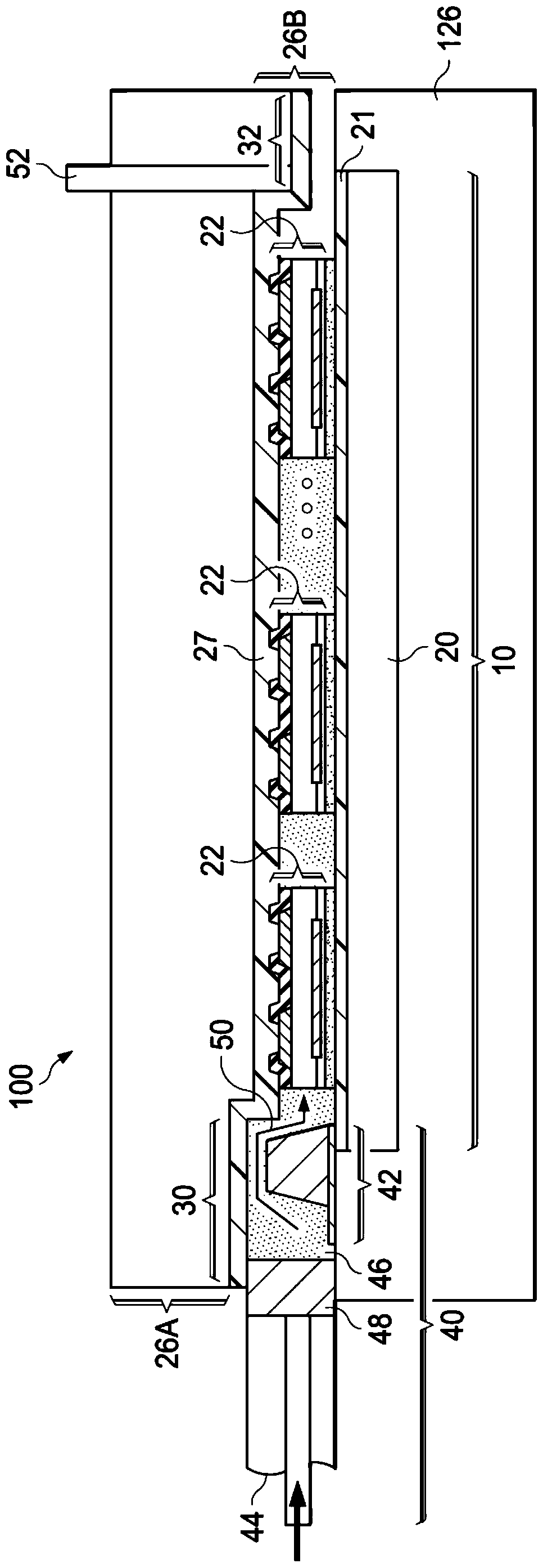
[0032] The following disclosure provides many different embodiments or examples for implementing different features of the invention. Specific examples of components and arrangements are described below to simplify the present disclosure. Of course, these are examples only and are not intended to limit the invention. For example, in the following description, forming a first component over or on a second component may include an embodiment in which the first component and the second component are formed in direct contact, and may also include an embodiment in which the first component and the second component are formed in direct contact. An embodiment in which an additional component may be formed between such that the first component and the second component may not be in direct contact. Furthermore, the present invention may repeat reference numerals and / or characters in various instances. This repetition is for the purposes of simplicity and clarity and does not in itsel...


PUM


Abstract

The invention provides a device including an encapsulation mold including a top and an annular edge having an annular shape. The annular edge is located below and connected to the edge of the top. The annular edge has an injection port and an exhaust port. The mold guide set is configured to be inserted into the injection port. The molded guide kit includes a front side wall with a curved front edge. The invention also provides a method of using the device.

Description

technical field [0001] The present invention relates generally to integrated circuit packaging and, more particularly, to wafer level packaging. Background technique [0002] In the packaging of integrated circuits, package components such as device dies and packaging substrates are typically stacked together by flip-chip bonding. To protect the stacked package components, a molding compound is distributed around the device die. [0003] Traditional molding methods include compression molding and transfer molding. Compression molding can be used for overmolding. Since compression molding cannot be used to fill the gaps between stacked dies, the underfill needs to be distributed in a different step than compression molding. Transfer molding, on the other hand, can be used to fill molded underfill into the gaps between and above the stacked package components. Thus, transfer molding can be used to distribute underfill and molding compound in the same step. However, transf...

Claims


Application Information

Patent Timeline
Patent Type & Authority Patents(China)
IPC IPC(8): B29C45/02B29C45/14B29C45/26B29C45/34H01L21/56
CPCH01L2224/16225H01L2924/18161B29C45/14836H01L21/561H01L21/565B29C45/14655B29C45/34B29C45/0046B29C45/02B29C2045/0049B29C2045/14663H01L24/18H01L24/96H01L24/97H01L2224/131H01L2224/16227H01L21/67126H01L2924/014H01L23/28H01L21/64B29L2031/34
Inventor 余振华刘重希黄晖闵黄致凡郑明达陈孟泽张博平黄见翎
Owner TAIWAN SEMICON MFG CO LTD
Features
  • R&D
  • Intellectual Property
  • Life Sciences
  • Materials
  • Tech Scout
  • Unparalleled Data Quality
  • Higher Quality Content
  • 60% Fewer Hallucinations
Learn More