
Four-guide-column type lifting machine

A technology of lifts and four guide columns, applied in the direction of lifting frames, lifting devices, etc., can solve problems such as risks and poor operation stability, and achieve the effect of simple and reliable structure, stable operation, and synchronous lifting

Inactive Publication Date: 2016-02-03
MIRACLE AUTOMATION ENG CO LTD
View PDF7 Cites 4 Cited by
  • Summary
  • Abstract
  • Description
  • Claims
  • Application Information

AI Technical Summary

Problems solved by technology

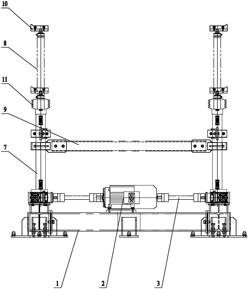
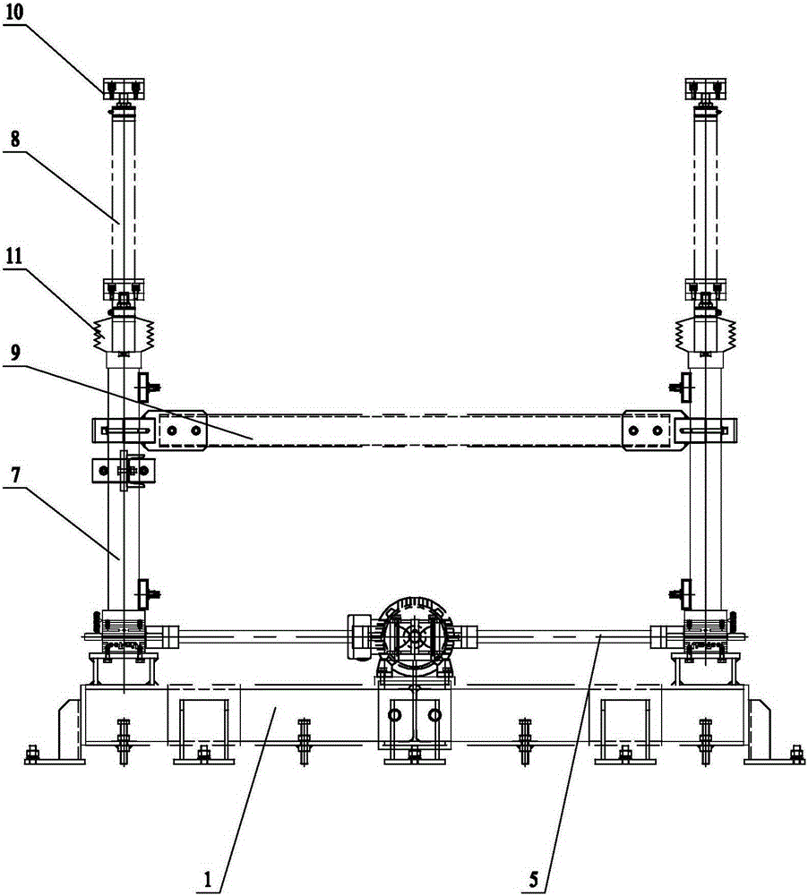
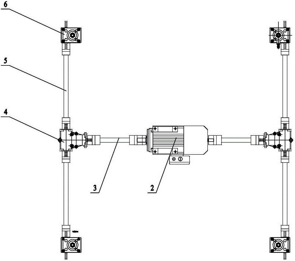
[0002] At present, the conventional four-column lift achieves synchronization through electronic control, which has risks and poor operational stability

Method used


Image

  • Four-guide-column type lifting machine
  • Four-guide-column type lifting machine
  • Four-guide-column type lifting machine

Examples


Embodiment Construction

[0012] The present invention will be further described below in conjunction with specific examples.

[0013] The four-column lift includes a base 1, a two-way output shaft motor 2, a first coupling 3, a commutator 4, a second coupling 5, a transmission box 6, a guide sleeve 7 and a guide column 8, and on the base 1 is fixed with a two-way output shaft motor 2 and four transmission boxes 6, the transmission box 6 has a screw input shaft, a guide sleeve 7 is fixed on each transmission box 6, and a guide column 8 is slidably installed in the guide sleeve 7, The bottom end of the guide column 8 is processed with external threads, and the bottom end of the guide column 8 is matched with the screw input shaft of the transmission box 6 through threads, and the centers of the four transmission boxes 6 are located on the four vertices of the same rectangle, and the two-way output shaft The motor 2 is located at the center of the rectangle where the four transmission boxes 6 are located...


PUM


Abstract

The invention relates to a four-guide-column type lifting machine. A bidirectional output shaft motor and four transmission cases are fixed to a base. The transmission cases are provided with screw input shafts. A guide sleeve is fixed to each transmission case. Guide columns are arranged in the guide sleeves in a sliding manner. External threads are machined at the bottom ends of the guide columns. The bottom ends of the guide columns are matched with the screw input shafts of the transmission cases through the threads. The centers of the four transmission cases are located at four peaks of the same rectangle. The bidirectional output shaft motor is located at the center position of the rectangle where the four transmission cases are located. First couplers are fixed to two output shafts of the bidirectional output shaft motor, and the other ends of the first couplers are connected with input shafts of commutators. Second couplers are fixed to output shafts of the commutators, and the other ends of the second couplers are connected with the screw input shafts of the transmission cases. The four-guide-column type lifting machine is of a pure mechanical structure and is simple and reliable in structure, and synchronous lifting and stable running are achieved.

Description

technical field [0001] The invention relates to a logistics machine, in particular to a four-column lift. Background technique [0002] At present, the conventional four-column lift is synchronized through electronic control, which has risks and poor operational stability. Contents of the invention [0003] The purpose of the present invention is to overcome the deficiencies in the prior art and provide a four-column lift that can realize synchronous lifting. [0004] According to the technical solution provided by the present invention, the four-column lift includes a base, a two-way output shaft motor, a first coupling, a commutator, a second coupling, a transmission box, a guide sleeve and a guide column. A two-way output shaft motor and four transmission boxes are fixed on the base. The transmission box has a screw input shaft. A guide sleeve is fixed on each transmission box. A guide column is slidably installed in the guide sleeve. The bottom end of the guide column...

Claims


Application Information

Patent Timeline
Patent Type & Authority Applications(China)
IPC IPC(8): B66F7/06B66F7/28
Inventor 蒋正兵杨雷
Owner MIRACLE AUTOMATION ENG CO LTD
Learn More