Lifting mechanism network and lifting mechanism synchronizing method

A lifting mechanism and lift technology, which is applied in the direction of lifting frame, lifting device, measuring device, etc., can solve the problems of unsynchronized lifting and lowering of the lift and other potential safety hazards, so as to achieve synchronous lifting, avoid potential safety hazards, and reduce potential safety hazards Effect

Inactive Publication Date: 2019-04-12
苏州艾沃意特汽车设备有限公司
View PDF7 Cites 3 Cited by
  • Summary
  • Abstract
  • Description
  • Claims
  • Application Information

AI Technical Summary

Problems solved by technology

[0004] The first purpose of the present invention is to provide a network of lifting mechanisms to solve the problem of asynchronous lifting of multiple lifts and reduce potential safety hazards

Method used


Image

  • Lifting mechanism network and lifting mechanism synchronizing method
  • Lifting mechanism network and lifting mechanism synchronizing method
  • Lifting mechanism network and lifting mechanism synchronizing method

Examples


no. 1 example

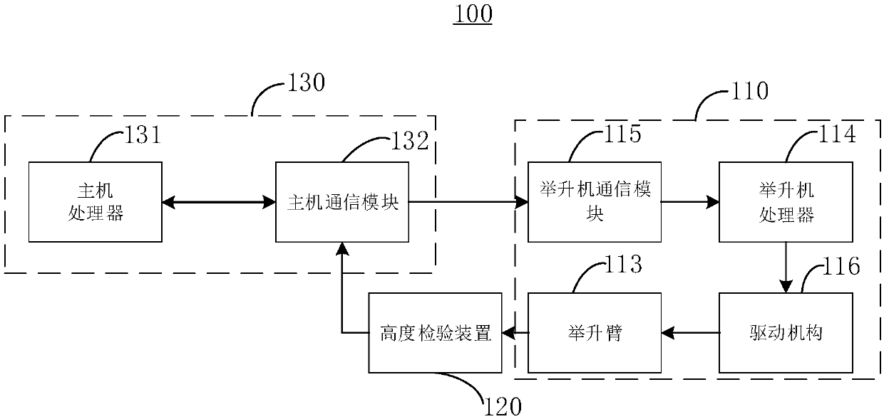
[0034] Please refer to Figure 1 to Figure 3 , the lifting mechanism network 100 provided by the present invention includes a plurality of lifts 110 , a plurality of height detection devices 120 and a host 130 . Each lift 110 is communicatively connected to the host computer 130 , and each height detection device 120 is communicatively connected to the host computer 130 , and the host computer 130 is used to adjust the lifting height of multiple lifts 110 .

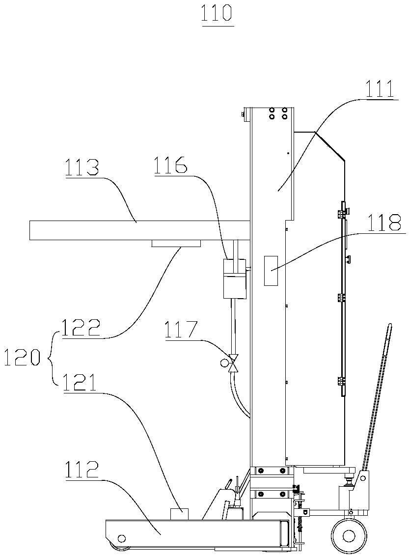
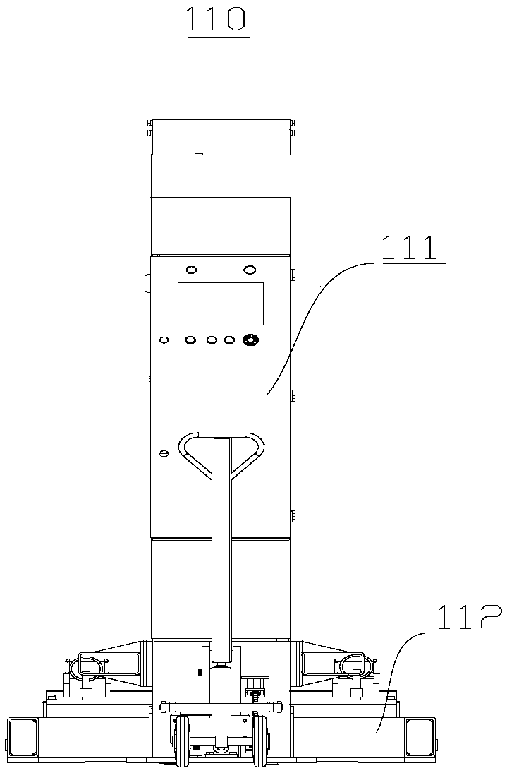
[0035] Further, each lift 110 includes a body 111 , a base 112 , a lift arm 113 , a driving mechanism 116 , a lift processor 114 , a lift communication module 115 and a card reader 118 .

[0036] Wherein, the lifting arm 113 is arranged on the fuselage 111, the base 112 is used for supporting the fuselage 111 and the lifting arm 113, and the lifting arm 113 is used for lifting the vehicle.

[0037]Further, the driving mechanism 116 of the lifting arm 113 of the lift 110 can be selected as a driving mechanism 116 such as ...

no. 2 example

[0050] The lifting mechanism synchronization method 200 provided in this embodiment is applied to the lifting mechanism networking 100 provided in the first embodiment, please refer to Figure 4 , the lifting mechanism synchronization method 200 includes:

[0051] 210: Before the lifting operation, the operator swipes the card to authorize the lift 110 to be lifted, so as to ensure that only the lift 110 that has been swiped is used for the lifting operation, and the host 130 receives the lift 110 Enter the authorization notice of the lifting mechanism network 100 , confirm the identity information of all the lifts 110 entering the lifting mechanism network 100 , and the operator starts the lifting operation of all the lifts 110 in the lifting mechanism network 100 .

[0052] 220: When all the lifts 110 in the lifting mechanism network 100 are performing lifting operations, each height detection device 120 of each lift 110 in the lifting mechanism network 100 checks the height...


PUM


Abstract

The invention relates to the field of engineering machinery, and provides a lifting mechanism network and a lifting mechanism synchronizing method. The lifting mechanism network comprises multiple lifting machines, multiple height detection devices and a host. Each height detection device in the lifting mechanism network detects the lifting height of each lifting arm in real time and sends a real-time detection signal to the host, the host calculates the rising and falling height of each lifting arm according to the detection signals sent by the multiple height detection devices, compares therising and falling heights of all the lifting arms and orders the multiple lifting machines in the lifting mechanism network to be adjusted to the same height. The multiple lifting machines, the multiple height detection devices, the host and communication among the multiple lifting machines, the multiple height detection devices and the host are configured, by means of the lifting mechanism network and the lifting mechanism synchronizing method, the lifting heights of all the lifting machines can be adjusted in real time, synchronous operation of all the lifting machines in the lifting mechanism network is achieved, and therefore the safety risk is greatly reduced.

Description

technical field [0001] The invention relates to the field of engineering machinery, in particular to a lifting mechanism networking and a lifting mechanism synchronization method. Background technique [0002] Lifts are often used to lift large vehicles. In actual operation, it is usually necessary to use an even number of lifts to lift at the same time. During the lifting operation, the lift often appears out of sync, which brings potential safety hazards to the lifting personnel on-site. [0003] At present, in actual operation, in order to reduce the inconsistency of movement between the lifts, the method of manual lifting operation is usually used for synchronization, which greatly affects the lifting efficiency and brings safety hazards to the lifting operators. Contents of the invention [0004] The first object of the present invention is to provide a network of lifting mechanisms to solve the problem of asynchronous lifting of multiple lifts and reduce potential s...

Claims


Application Information

Patent Timeline
Patent Type & Authority Applications(China)
IPC IPC(8): B66F7/28G01B21/02
CPCB66F7/28G01B21/02
Inventor 张书军张捷于业清郑传兵
Owner 苏州艾沃意特汽车设备有限公司
Why Eureka
Try Eureka