
Formwork for cast-in-place concrete stair steps

A technology for concrete and stairs, which is applied to formwork/formwork/work frame, on-site preparation of building components, construction, etc., can solve the problems of slow setting speed, low precision of formwork, affecting the construction of other types of work, etc. The effect of fast setting speed and high precision of mold support

Inactive Publication Date: 2017-06-16
CHINA CONSTR SEVENTH ENG DIV SHANGHAI CORP
View PDF5 Cites 2 Cited by
  • Summary
  • Abstract
  • Description
  • Claims
  • Application Information

AI Technical Summary

Problems solved by technology

[0002] The stairs of the vast majority of buildings at present all adopt cast-in-place reinforced concrete stairs, and the key process that affects the quality of cast-in-place reinforced concrete stairs is the support of formwork, and the difficulty of formwork support lies in the formwork support of stair steps. The formwork for stepping is usually processed and supported by square wood and formwork on site. The problem is that this process not only has a slow setting speed, low precision of formwork, and takes up a large area of ​​construction, which not only seriously affects the construction of other types of work, but also produces a lot of In addition, due to the complete on-site manual support, the regularity of the mold is poor, and the phenomenon of missing edges and corners of the reinforced concrete stairs after construction is unavoidable, and the appearance quality is also relatively poor;
[0003] In order to improve the above-mentioned construction defects, the existing technology also uses combined steel formwork to implement the formwork for stair steps. Although this process reduces the use of wooden formwork, reduces the waste of resources, and improves the appearance quality, but the existing problems are , the steps of the stairs still need step-by-step formwork support step by step, the support speed cannot be increased, the distance between the steps is controlled by humans, and the current situation of low formwork accuracy and large errors is still unavoidable

Method used


Image

  • Formwork for cast-in-place concrete stair steps
  • Formwork for cast-in-place concrete stair steps
  • Formwork for cast-in-place concrete stair steps

Examples


Embodiment Construction

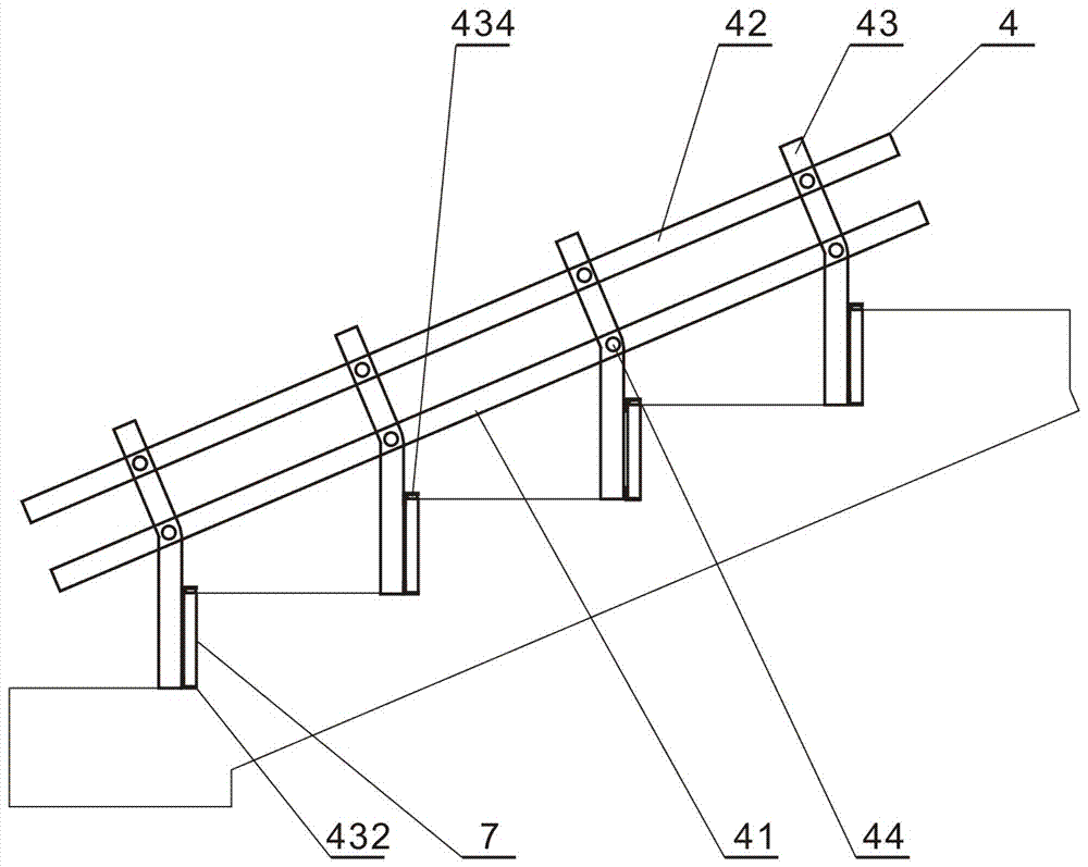
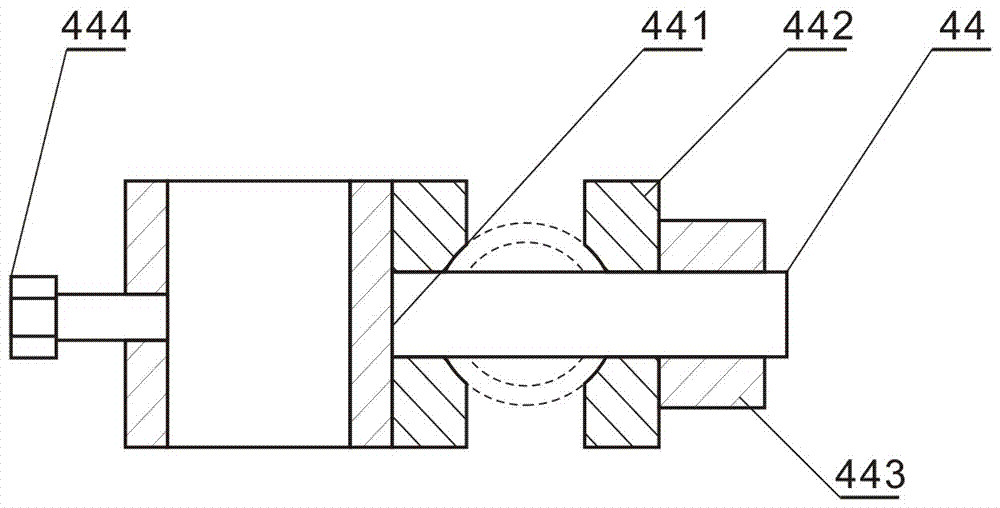
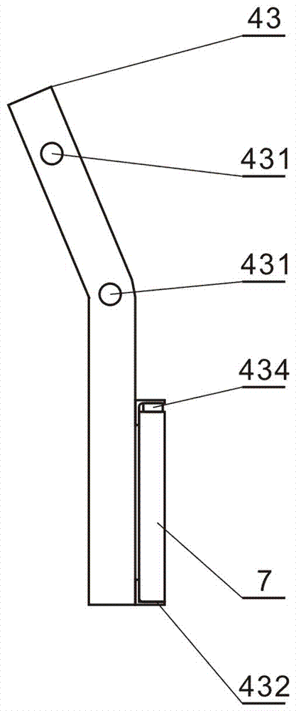
[0016] refer to figure 1 , figure 2 , image 3 , Figure 4 , the present invention comprises a step side panel 4, a horizontal bar 5, a cross fastener 6 and a step vertical plate 7, and the step side panel 4 is composed of a main longitudinal bar 41, an auxiliary longitudinal bar 42, a step adjustment bar 43 and a step joint 44 , the main longitudinal bar 41 and the auxiliary longitudinal bar 42 are arranged in parallel, and the stepping adjustment bars 43 are several pieces, and they are arranged in parallel with the main longitudinal bar 41 and the auxiliary longitudinal bar 42 to overlap in the shape of a "well", and the stepping joints 44 are several pieces, and respectively Hinge the overlapping nodes between the main longitudinal bar 41, the auxiliary longitudinal bar 42 and the step adjusting bar 43 sequentially;

[0017] The step side piece 4 is two pieces arranged side by side on both sides of the stair step, and the main longitudinal bar 41 and the secondary long...


PUM


Abstract

The invention discloses a formwork of a cast-in-place concrete stair step. The formwork of the cast-in-place concrete stair step comprises two step side plates, a horizontal transverse rod, a cross-shaped fastener and a step vertical plate, wherein the step side plate consists of a main longitudinal rod, a secondary longitudinal rod, a plurality of step adjusting rods and a plurality of step joints; the main longitudinal rod and the secondary longitudinal rod are parallel to each other; the step adjusting rods, the main longitudinal rod and the secondary longitudinal rod are intersected with each other and are in lap joint to form a '#'-shaped object; joints through which the main longitudinal rod, the secondary longitudinal rod and the step adjusting rods are in lap joint are sequentially hinged to one another by the step joints; and the two step side plates are arranged on two sides of the stair step side by side. Pre-mounted step side plate structures are adopted, and interval positioning and erection of multiple stair steps can be finished at one step. The formwork of the cast-in-place concrete stair step has the advantages of high erection speed and high form erecting precision; and the step side plates can be transferred and used repeatedly, and requirements of erection of stair steps at different intervals can be met.

Description

technical field [0001] The invention relates to formwork support in the technical field of building construction, in particular to a formwork for cast-in-place concrete stair steps. Background technique [0002] The stairs of the vast majority of buildings at present all adopt cast-in-place reinforced concrete stairs, and the key process that affects the quality of cast-in-place reinforced concrete stairs is the support of formwork, and the difficulty of formwork support lies in the formwork support of stair steps. Prior art stairs The formwork for stepping is usually processed and supported by square wood and formwork on site. The problem is that this process not only has a slow setting speed, low precision of formwork, and takes up a large area of ​​construction, which not only seriously affects the construction of other types of work, but also produces a lot of In addition, due to the complete on-site manual support, the regularity of the mold is poor, and the phenomenon ...

Claims


Application Information

Patent Timeline
Patent Type & Authority Patents(China)
IPC IPC(8): E04G13/06
Inventor 方威
Owner CHINA CONSTR SEVENTH ENG DIV SHANGHAI CORP
Learn More