
A Design Method for the Moving Beam Structure of Flying Probe Testing Machine

A technology of flying probe testing machine and design method, which is applied in the direction of electronic circuit testing, parts and calculations of electrical measuring instruments, etc., can solve problems such as cumbersome optimization process, and achieve the effect of simple structure, convenient installation and light weight

Active Publication Date: 2018-11-27
HANS CNC SCI & TECH
View PDF6 Cites 0 Cited by
  • Summary
  • Abstract
  • Description
  • Claims
  • Application Information

AI Technical Summary

Problems solved by technology

[0004] For the optimization of the motion structure, it often involves more parameters, and also involves the matching of the joint and the corresponding structure. The whole optimization process is relatively cumbersome.

Method used


Image

  • A Design Method for the Moving Beam Structure of Flying Probe Testing Machine
  • A Design Method for the Moving Beam Structure of Flying Probe Testing Machine
  • A Design Method for the Moving Beam Structure of Flying Probe Testing Machine

Examples


Embodiment Construction

[0034] In order to facilitate the understanding of the present invention, the present invention will be described more fully below with reference to the relevant drawings. The preferred embodiments of the invention are shown in the drawings. However, the present invention can be implemented in many different forms and is not limited to the embodiments described herein. On the contrary, the purpose of providing these embodiments is to make the understanding of the disclosure of the present invention more thorough and comprehensive.

[0035] Unless otherwise defined, all technical and scientific terms used herein have the same meaning as commonly understood by those skilled in the technical field of the present invention. The terminology used in the specification of the present invention herein is only for the purpose of describing specific embodiments, and is not intended to limit the present invention.

[0036] Refer to figure 1 As shown, the present invention provides a method f...


PUM


Abstract

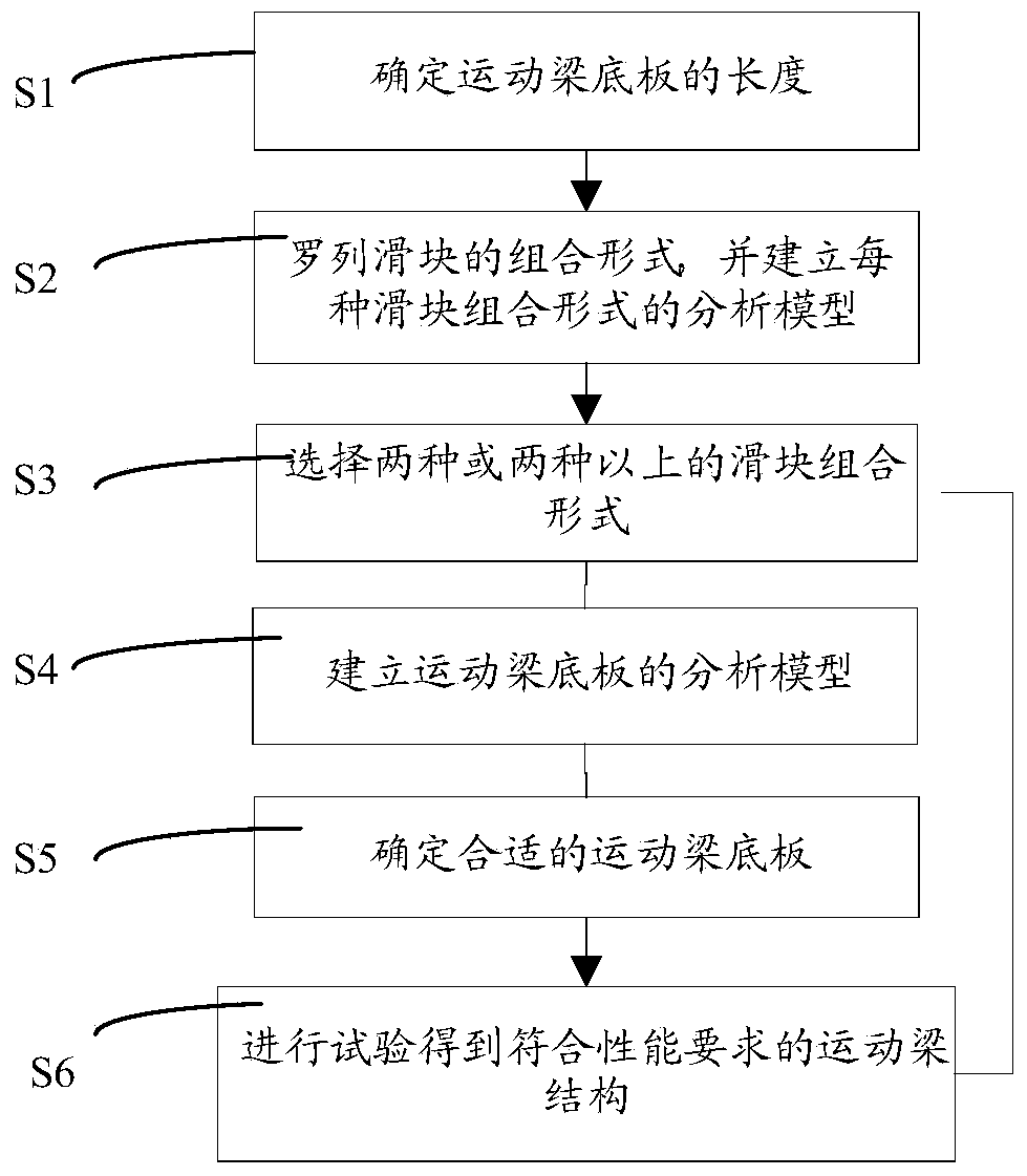
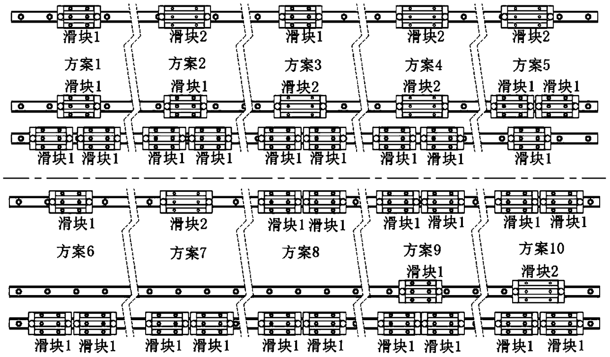
The invention relates to the technical field of a printed circuit board test, and discloses a design method of a flying probe tester motion beam structure. According to the design method, first of all, the length of a motion beam base plate is determined, the span of slide blocks at the two ends of the base plate is determined accordingly, combination forms of different slide blocks are designed, the combination forms of each kind of slide blocks are analyzed by use of a multi-rigid-body dynamic analysis method, features of the motion beam structure under the combination forms of each kind of slide blocks are obtained, proper slide block combination forms are selected, a proper base plate structure is determined, the base plate of the motion beam structure is modified to accord with performance and processing requirements, the motion beam structure is tested, and thus the motion beam structure according with a performance requirement is obtained. According to the invention, by use of the multi-rigid-body motion force and flexible motion mechanics analysis method, the combination portion of the motion beam structure and the motion beam base plate are analyzed and optimized respectively, and the motion beam structure with high performance can be rapidly and effectively designed.

Description

Technical field [0001] The invention relates to the technical field of printed circuit board testing, and more specifically, to a design method of a moving beam structure of a flying probe test machine. Background technique [0002] The flying probe tester is an important equipment for PCB electrical measurement. Through the technical coupling with multiple motors and screw rods or other transmission components, it drives the rapid movement of the test head to realize the contact between the probe and the pad or device pin and conduct electrical measuring. With the continuous development of the electronics industry, the size of electronic products continues to decrease, which makes the circuit size of the PCB board smaller and higher, and the density is getting higher and higher. This puts higher requirements on the performance of the test equipment, that is, faster Fast positioning speed and higher positioning accuracy. [0003] At present, the high-speed and high-precision flyi...

Claims


Application Information

Patent Timeline
Patent Type & Authority Patents(China)
IPC IPC(8): G06F17/50G01R31/28G01R1/02
Inventor 陈楚技王星李宁廉成翟学涛高云峰
Owner HANS CNC SCI & TECH
Learn More