Stretch-bending process model correction method based on workpiece three-dimension scanning

A process model and three-dimensional scanning technology, applied in special data processing applications, instruments, electrical digital data processing, etc., can solve problems such as difficulty in meeting accuracy requirements, large rebound, and difficulty in meeting accuracy requirements

Inactive Publication Date: 2013-11-27
NORTHWESTERN POLYTECHNICAL UNIV +1
View PDF3 Cites 32 Cited by
  • Summary
  • Abstract
  • Description
  • Claims
  • Application Information

AI Technical Summary

Problems solved by technology

Traditionally, the stretch bending die is designed according to the inner surface of the profile part. Due to the large rebound of the profile part after unloading, the traditional design method of the stretch bending die makes it difficult to meet the precision requirements after the part is formed; currently, in the field of profile stretch bending The common method is to obtain springback data through numerical simulation technology, and define the process model according to the springback data. However, there are inevitable errors in the numerical simulation process. It is generally believed in the industry that the error is about 30%, which leads to the It is difficult to meet the precision requirements after stretch bending, and manual calibration is still required

Method used


Image

  • Stretch-bending process model correction method based on workpiece three-dimension scanning
  • Stretch-bending process model correction method based on workpiece three-dimension scanning
  • Stretch-bending process model correction method based on workpiece three-dimension scanning

Examples


Embodiment Construction

[0035] Describe the present invention below in conjunction with specific embodiment:

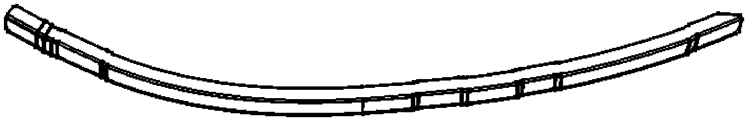
[0036] by figure 1 Take the part shown as an example. This part is a variable curvature, with sag, and asymmetrical L-shaped section profile part. Since the forming accuracy of the part formed according to the existing process model is not enough, the process model of the part needs to be corrected. The specific implementation process of the correction of the process model based on the three-dimensional scanning model of the workpiece is described below in conjunction with the accompanying drawings:

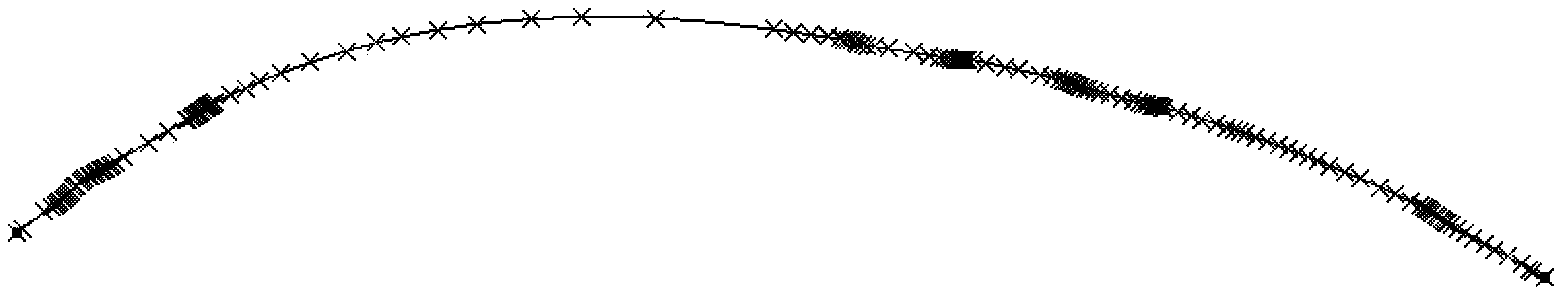
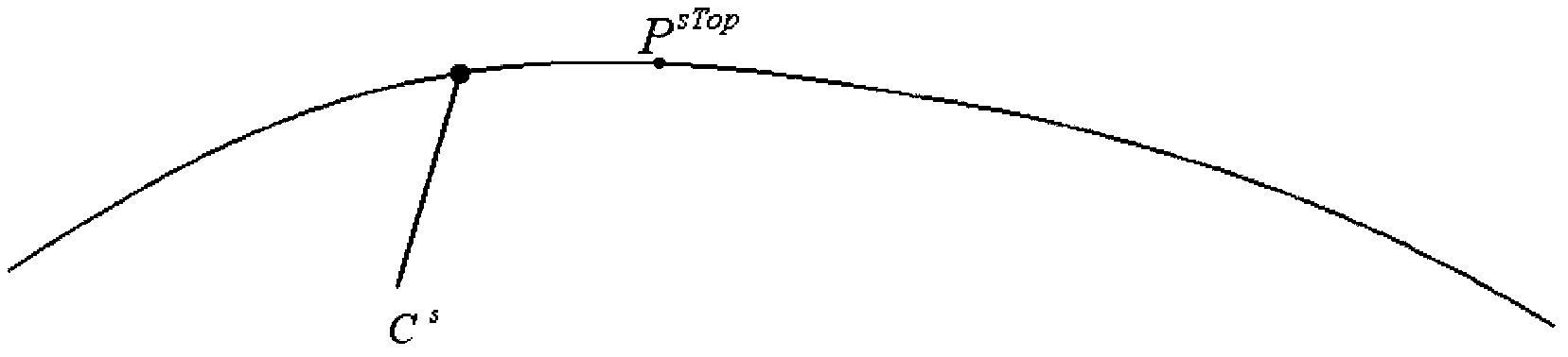
[0037] Step 1: Based on the initial process model M g The workpiece obtained by stretch bending is scanned to obtain the workpiece scanning model M s , for M s Perform contour line extraction and de-sag processing to obtain a non-sag contour line C s ,Specific steps are as follows:

[0038] Step 1.1: Use model comparison software to compare M s and the workpiece design model M d For comp...


PUM


Abstract

The invention provides a stretch-bending process model correction method based on workpiece three-dimension scanning. The stretch-bending process model correction method based on the workpiece three-dimension scanning comprises the steps of (1) carrying out comparison on a scanning model contour line of a fetched workpiece and a discrete design model contour line, obtaining the distance between every two endpoints of each section, (2) calculating the radius value of each discrete section of the scanning model contour line, carrying out difference calculation between the radius value of each discrete section of the scanning model contour line and the radius value of each subsection circular arc of the design model contour line to obtain the compensation values of subsection circular arcs of an existing process model contour line to obtain a corrected process model contour line, and (3) using the CAD software to carry out scanning on the corrected process model contour line to obtain a corrected process model. The stretch-bending process model correction method based on the workpiece three-dimension scanning carries out correction on the resilience value of numerical simulation calculation on the basis of the workpiece three-dimension scanning, solves the problem of errors generated by process model definition on the basis of numerical simulation, reduces manpower and material resources consumed by manual shape correction, analyzes the generation positions and the magnitude of the forming errors through comparison between a workpiece three-dimension scanning model and a design model, and can rapidly and accurately modify the process models of sectional material parts.

Description

technical field [0001] The invention relates to the technical field of mechanical manufacturing, specifically a method for correcting a stretch bending process model based on three-dimensional scanning of a workpiece, which is applied to the correction of a process model of a two-dimensional variable curvature profile part, and uses the corrected process model as a tool for designing and manufacturing a stretch bending die. in accordance with. Background technique [0002] Profile parts are widely used in the field of machinery manufacturing, especially in the field of aircraft manufacturing technology. Profile parts are the main structural parts that constitute the aircraft skeleton, and are often used in frame ribs and fuselage stringers. The profile of profile parts is complex, generally asymmetrical, and has variable curvature. Nowadays, the more common method is to obtain the required mold surface in the stretch bending process through a large number of experiments or n...

Claims


Application Information

Patent Timeline
Patent Type & Authority Applications(China)
IPC IPC(8): G06F17/50
Inventor 王俊彪董伟刘闯徐龙李仁花
Owner NORTHWESTERN POLYTECHNICAL UNIV
Why Eureka
Try Eureka