Sparse beam pattern comprehensive designing method

A technology of comprehensive design and beam diagram, applied in the field of comprehensive design of sparse beam diagram, can solve problems such as limitations and inaccuracy

Inactive Publication Date: 2017-05-17
NORTHWESTERN POLYTECHNICAL UNIV
View PDF1 Cites 12 Cited by
  • Summary
  • Abstract
  • Description
  • Claims
  • Application Information

AI Technical Summary

Problems solved by technology

[0004] The purpose of the present invention is to provide a sparse beam pattern comprehensive design method, which solves the limitation

Method used


Image

  • Sparse beam pattern comprehensive designing method
  • Sparse beam pattern comprehensive designing method
  • Sparse beam pattern comprehensive designing method

Examples


Embodiment

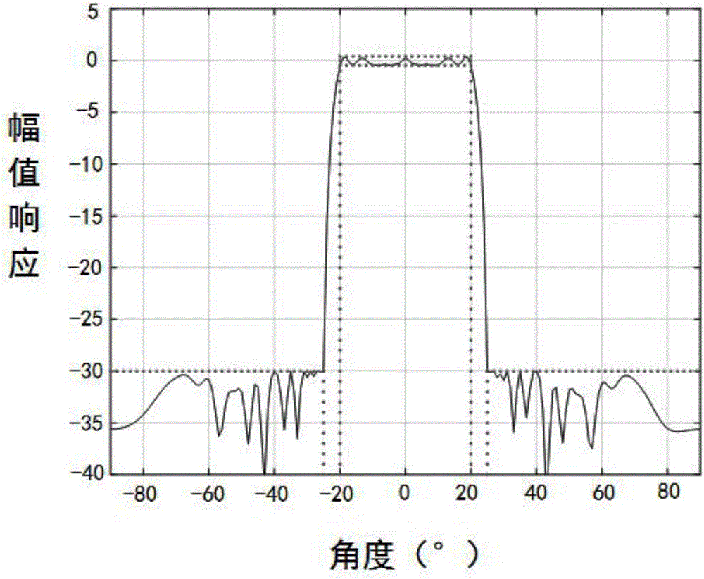
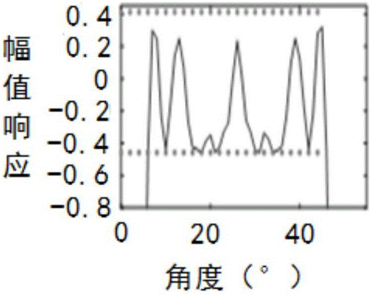
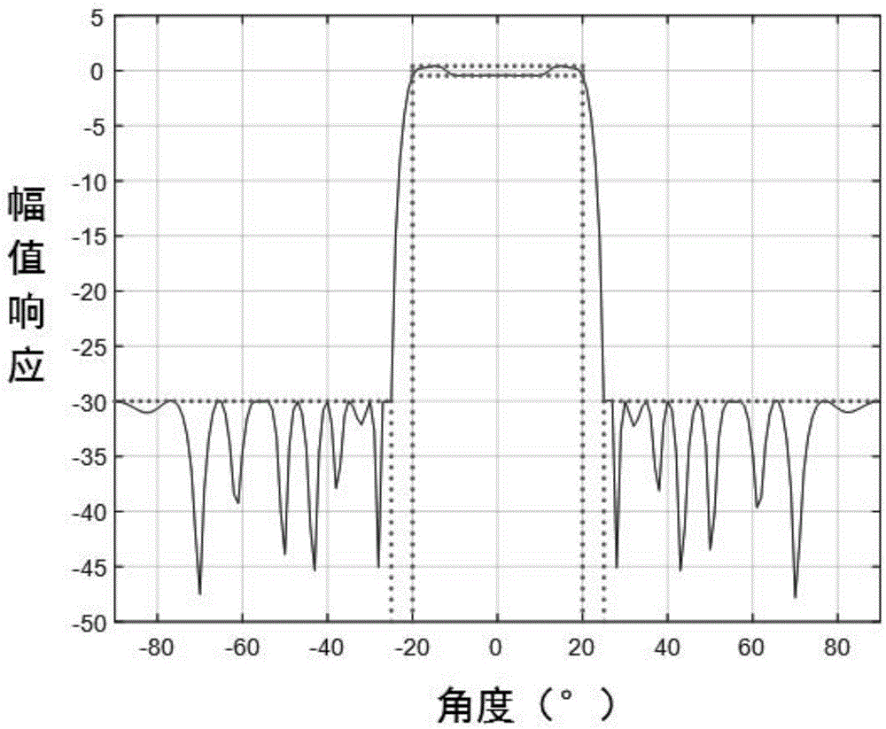
[0230] There is an array system composed of 41 non-uniformly spaced sensors, the design requirements are: main lobe width [-20, 20], ripple coefficient ε=0.1, main lobe ripple width interval [-0.4576 0.4139]db, side Lobe width [-90 -25]∪[25 90], upper bound coefficient η=-30db;

[0231] Build a weight optimization model with sparse constraints:

[0232]

[0233] According to the ADMM algorithm, the auxiliary variable u is introduced m ,v s , divided into step ①, step ② and step ③ cycle optimization:

[0234] Step ①, fixed w(t), solve for v s ,u m ;

[0235] Step ②, fixed u m (t+1), v s (t+1), solve for w;

[0236] Introduce auxiliary variable z, let z=w;

[0237] Step I, fix w(t), λ r (t),λ i (t), solve for z;

[0238] Step II, fix z(t+1),λ r (t),λ i (t), solve for w;

[0239] Step III, fix z, w, find λ;

[0240] Loop iteration step I, step II and step III until z, w, λ converge;

[0241] Step ③, fix u m (t+1), v s (t+1), w, find λ m ,κ s ;

[0242...


PUM


Abstract

The invention discloses a sparse beam pattern comprehensive designing method. The method specifically includes: step 1, in an actual array signal system, according to designing requirements, building a weight optimization objective model taking p norm (0<p<2) as sparse constraint, and setting constraint conditions of main lobe width, ripple wave width and side lobe limitation according to requirements; step 2, after the step 1 is completed, aiming at a non-convex optimization model, adopting an alternating method multiplier method to iteratively sparse weight coefficient w; step 3, utilizing the sparse weight coefficient w acquired in the step 2, and combining computer simulation software to make beam pattern according to designing requirements. By the method, the problems of boundedness and inaccuracy in the prior art are solved, and complexity of an actual array system and actual application cost are lowered.

Description

technical field [0001] The invention belongs to the technical field of array signal processing methods, and in particular relates to a sparse beam pattern comprehensive design method. Background technique [0002] In recent years, array signal processing technology has been widely used in the field of wireless communication. An important part of it is beamforming technology. Its essence is to achieve the purpose of enhancing the desired signal and suppressing interference by weighting each array element and performing spatial filtering. [0003] Beam pattern comprehensive design technology is a key technology in the field of array signal processing, and has been widely used in radar, sonar, electronic surveillance and seismic detection and other fields. When imprecise or ambiguous direction-of-arrival estimates are expected, the robustness of the estimates can be improved by controlling the mainlobe beamwidth and response ripple of the radiation beam pattern. Traditional be...

Claims


Application Information

Patent Timeline
IPC IPC(8): G06F17/50
CPCG06F30/20G06F2111/06
Inventor 梁军利张旋
Owner NORTHWESTERN POLYTECHNICAL UNIV
Why Eureka
Try Eureka