Melting path design method for high energy beam selective melting forming

A technology of selective melting and design method, which is applied in the direction of additive processing, etc., can solve the problems that material powder or metal wire can only be melted point by point or partition, adverse effects on accuracy and mechanical properties, uneven heating of materials, etc., to achieve melting Reasonable path design, low input cost, and convenient effect

Active Publication Date: 2015-12-30
西安赛隆增材技术股份有限公司
View PDF6 Cites 29 Cited by
  • Summary
  • Abstract
  • Description
  • Claims
  • Application Information

AI Technical Summary

Problems solved by technology

Nowadays, the high-energy beams used for additive manufacturing mainly include electron beams and laser beams. Due to the limitation of energy density and material characteristics, the layered manufacturing process of high-energy beam selective melting and forming is to complete the melting and forming of materials through one-time scanning. , can only be heated point by point or block, material powder or wire can only be melted point by point or partition
At present, the point-by-point or block-by-block scanning melting method adopte

Method used


Image

  • Melting path design method for high energy beam selective melting forming
  • Melting path design method for high energy beam selective melting forming
  • Melting path design method for high energy beam selective melting forming

Examples


Embodiment Construction

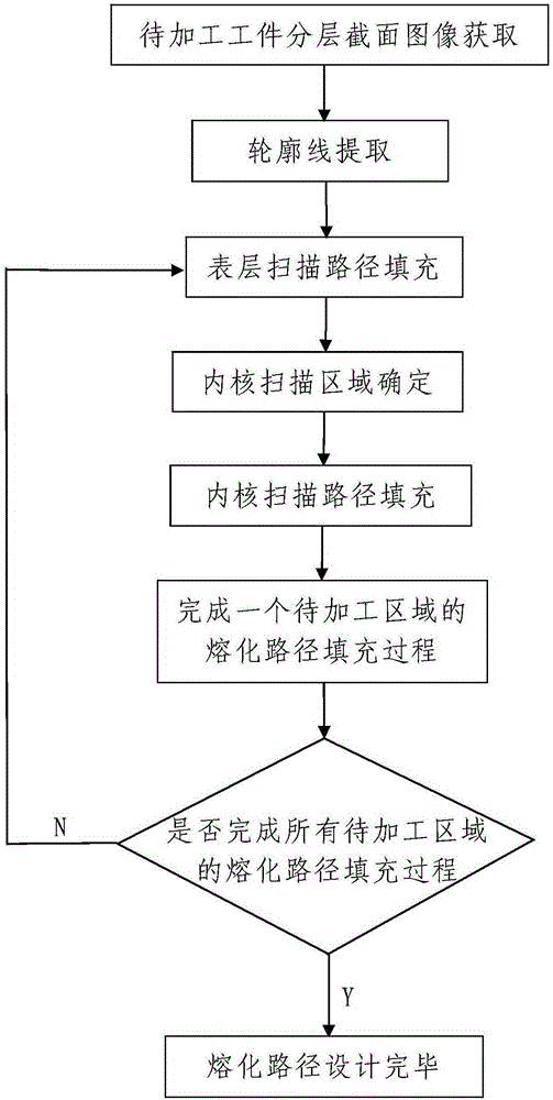
[0066] Such as figure 1 A method for designing a melting path of high-energy beam selective melting forming includes the following steps:

[0067] Step 1. Acquisition of layered cross-sectional images of the workpiece to be processed: obtaining multiple layered layered cross-sectional images of the workpiece to be processed, and storing the obtained multiple layered cross-sectional images in the data processing device;

[0068] A plurality of the layers are arranged from bottom to top and they are arranged in parallel, and the layer thickness of each layer is the same as the layer thickness when the workpiece to be processed is melted and formed layer by layer by the high-energy beam selective melting forming method ;

[0069] The layered section of each layer is an area to be processed, and each image of the layered section is an image of the area to be processed; the area to be processed is formed by selective melting using a high-energy beam area, the high-energy beam is ...


PUM


Abstract

The invention discloses a melting path design method for high energy beam selective melting forming. The method comprises the following steps: 1, acquisition of layered section images of a to-be-machined workpiece: layered section images of multiple layers of the to-be-machined workpiece are acquired and stored, wherein the section of each layer is a to-be-machined area; 2, contour extraction: the contour of each layer of section image is extracted; 3, melting path filling: melting path filling is performed on the multiple to-be-machined areas respectively, melting path filling for any to-be-machined area comprises the following steps: surface layer scanning path filling, inner core scanning area determining and inner core scanning path filling. The method has simple steps and is reasonable in design, convenient to implement and good in use effect; a melting path for high energy beam selective melting forming can be designed simply, conveniently and rapidly, the designed melting path is reasonable, the workpiece machining precision is high, all parts of the workpiece are uniformly heated, and the workpiece has excellent mechanical properties.

Description

technical field [0001] The invention belongs to the technical field of high-energy beam processing, and in particular relates to a melting path design method for high-energy beam selective melting forming. Background technique [0002] High-energy beam selective melting technology is an advanced additive manufacturing technology. Firstly, the target part model is designed by computer, and then the model is layered by software to obtain the cross-section information of the part. After superposition layer by layer, the high-energy beam is controlled layer by layer according to the cross-section information The metal powder is melted and piled up in such a way that the target part is finally made. High-energy beam selective melting technology can quickly and directly obtain metal parts of any complex shape without making molds. It is an effective way to solve the manufacturing of complex technical parts, shorten the production cycle, increase productivity and reduce production ...

Claims


Application Information

Patent Timeline
IPC IPC(8): B22F3/105B33Y50/00
Inventor 全俊涛赵培周勃延贾文鹏朱纪磊向长淑
Owner 西安赛隆增材技术股份有限公司
Why Eureka
Try Eureka