Reversing valve used for conveying silica gel mill base

A reversing valve and color paste technology, applied in the field of reversing valves, can solve the problems of reversing valve failure, high viscosity of silica gel color paste, and easy adhesion on the inner wall of the channel inside the reversing valve, etc., to achieve structural Simple, reduce the effect of reversing valve clogging

Active Publication Date: 2016-02-03
DONGGUAN LIANGCAI SILICONE ELECTRONICS TECH CO LTD
View PDF6 Cites 3 Cited by
  • Summary
  • Abstract
  • Description
  • Claims
  • Application Information

AI Technical Summary

Problems solved by technology

In the injection molding of liquid silicone material, the reversing valve is mainly used on the proportional metering cylinder to meet the flow direction state required for the liquid silicone color paste to flow into and out of the metering cylinder, while the structure of the internal channel of the reversing valve on the existing metering cylinder is relatively Complex, and the silicone color paste itself has a high viscosity, which is easy to adhere to the inner wall of the channel inside the reversing valve, causing blockage and causing the reversing valve to fail

Method used


Image

  • Reversing valve used for conveying silica gel mill base
  • Reversing valve used for conveying silica gel mill base
  • Reversing valve used for conveying silica gel mill base

Examples


Embodiment Construction

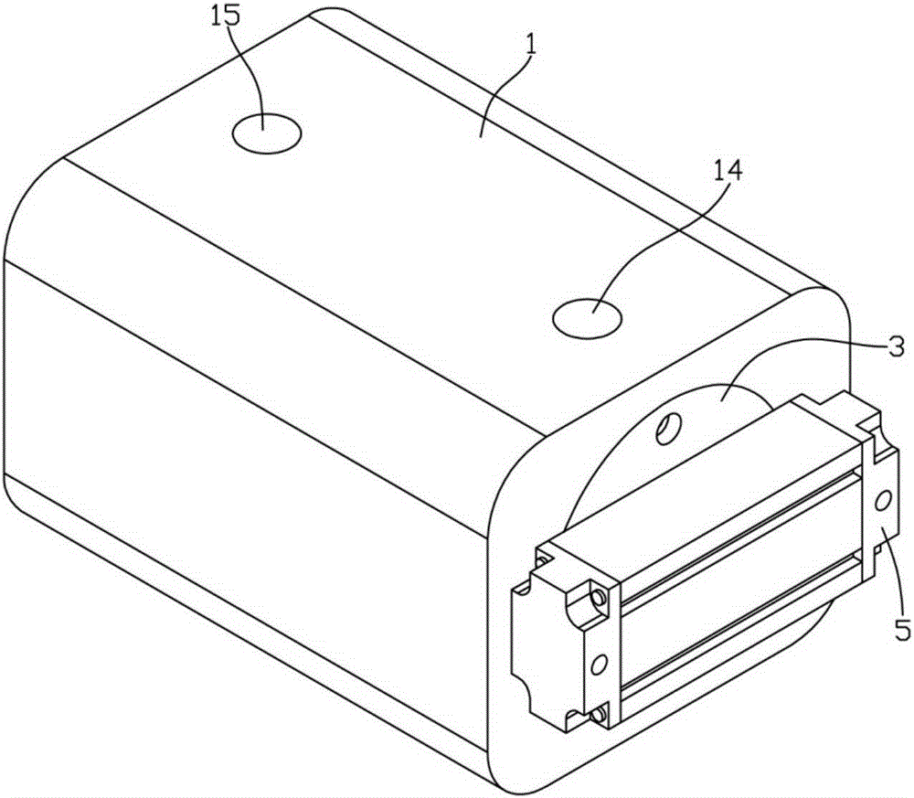
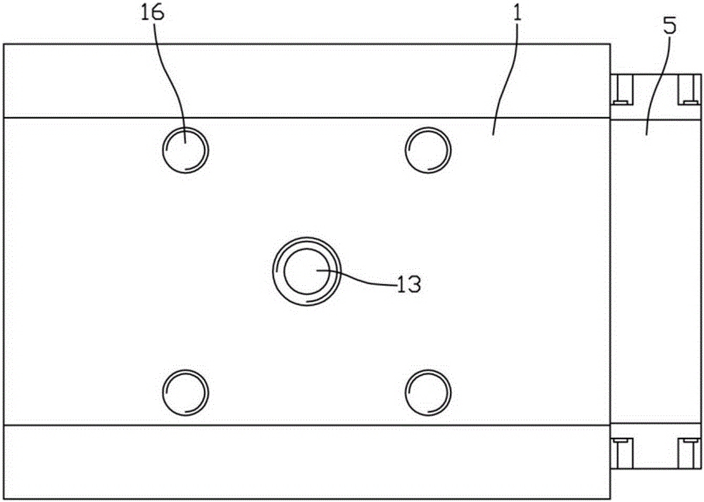
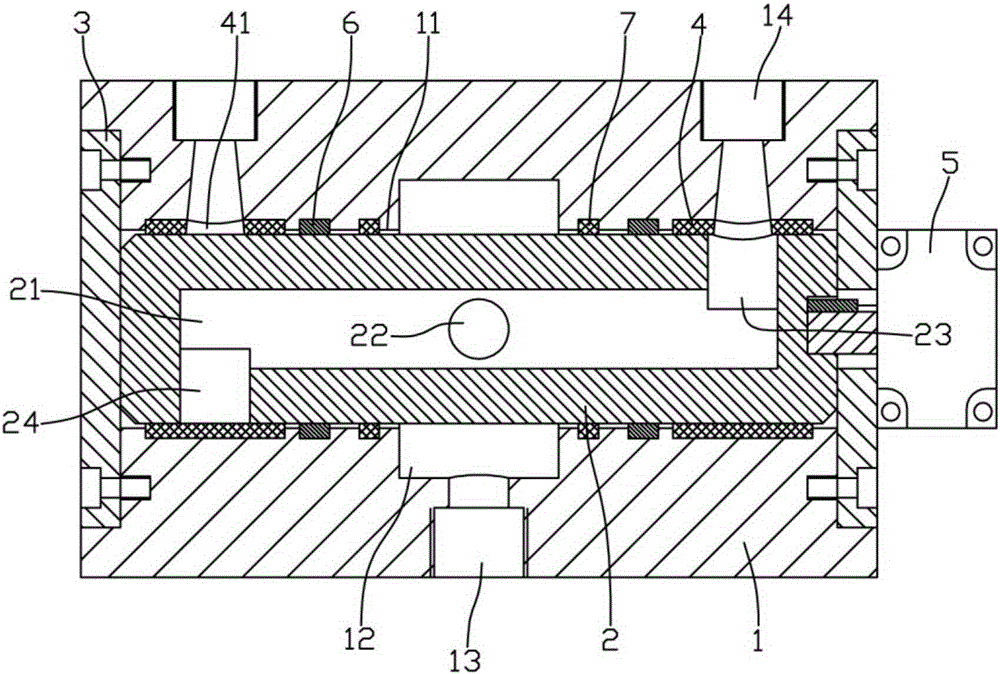
[0018] Example: see Figures 1 to 4 As shown in the figure, a reversing valve used for conveying silica gel color paste includes a valve seat 1 and a cylindrical valve core 2. The valve core hole 11 is formed on the valve seat 1 and runs through the end faces of the left and right sides, and the valve core hole 11 is inserted Connected with the valve core 2, an annular groove 12 is formed on the inner wall of the middle part of the valve core hole 11 of the valve seat 1, and a reversing hole 13 penetrating through the lower end surface of the valve seat 1 is formed on the inner wall of the annular groove 12, and on the inner wall at both ends of the valve core hole 11 The input hole 14 and the output hole 15 are respectively formed through the upper end surface of the valve seat 1; the left and right end surfaces of the valve core 2 are against the end cover 3, and the end cover 3 is fixedly connected to the left and right end surfaces of the valve seat 1;

[0019] A channel 2...


PUM


Abstract

The invention discloses a reversing valve used for conveying a silica gel mill base. The reversing valve comprises a valve seat and a cylindrical valve element, wherein a valve element hole penetrating through the left end surface and the right end surface is formed in the valve seat; the valve element is inserted into the valve element hole; an annular groove is formed in the inner wall of the middle of the valve element hole of the valve seat; a reversing hole penetrating through the lower end surface of the valve seat is formed in the inner wall of the annular groove; an input hole and an output hole penetrating through the upper end surface of the valve seat are formed in the inner walls of the two ends of the valve element hole respectively; the left and right end surfaces of the valve element abut against an end cover, and the end cover is fixedly connected with the left and right end surfaces of the valve seat; a passage extending in the axial direction of the valve element is formed in the valve element, a through hole penetrating through the outer wall of the valve element is formed in the inner wall of the middle of the passage and is communicated with the annular groove in the valve seat, and an input groove hole and another input groove hole penetrating through the outer wall of the valve element are formed in the inner walls of the two ends of the through hole respectively. The reversing valve used for conveying the silica gel mill base is simple in structure, an internal reversing passage structure facilitates flowing of the mill base, the mill base is not prone to causing blockage of the inside of the reversing valve, and therefore the phenomenon of blockage of the reversing valve is reduced.

Description

Technical field: [0001] The invention relates to the technical field of valve bodies, and more specifically relates to a reversing valve applied to conveying silica gel color paste. Background technique: [0002] The reversing valve is a valve that realizes liquid communication, cut-off and reversing, as well as pressure unloading and sequential action control. In the injection molding of liquid silicone material, the reversing valve is mainly used on the proportional metering cylinder to meet the flow direction state required for the liquid silicone colorant to flow into and out of the metering cylinder, while the structure of the inner channel of the reversing valve on the existing metering cylinder is relatively Complicated, and the silicone color paste itself has a high viscosity, which is easy to adhere to the inner wall of the channel inside the reversing valve, causing blockage and causing the reversing valve to fail. Invention content: [0003] The purpose of the ...

Claims


Application Information

Patent Timeline
Patent Type & Authority Applications(China)
IPC IPC(8): F16K11/085
CPCF16K11/085
Inventor 何忠翰
Owner DONGGUAN LIANGCAI SILICONE ELECTRONICS TECH CO LTD
Why Eureka
Try Eureka