
An ignition circuit applied to electric explosive device

An ignition circuit and device technology, applied in blasting and other directions, can solve the problems such as the ignition circuit cannot be ignited normally, the ignition sequence of the electric explosion device group fails, and the normally open contacts work asynchronously.

Active Publication Date: 2016-11-30
中国航天科技集团公司第四研究院第四十一研究所
View PDF6 Cites 0 Cited by
  • Summary
  • Abstract
  • Description
  • Claims
  • Application Information

AI Technical Summary

Problems solved by technology

[0005] The application of short-circuit plugs to implement short-circuit protection for electric explosive devices is realized through the docking of electrical connectors, and the reliability is high; however, a special cover needs to be set up on the bulkhead for disassembly or installation of short-circuit plugs, and staff are required each time Manual operation is not conducive to the application of tasks with relatively short time requirements (such as launch site testing / launching) or missile packing for long-term storage
[0006] When the two sets of normally open contacts of a single relay are used to control the on-off of the positive and negative ignition circuits of the electric explosion device respectively, and when the ignition of the electric explosion device is completed, if the two sets of normally open contacts of the relay do not act normally, or due to When the relay itself has a fault and cannot be pulled in, it will cause the ignition circuit to fail to ignite normally; if the two sets of normally open contacts of a single relay connected to the positive and negative ignition circuits of the electric explosion device do not work synchronously, it will cause the entire The ignition timing of the electric explosive device group fails or the timing is abnormal
[0007] When the two sets of normally open contacts of two relays are used in parallel to control the on-off of the positive and negative ignition circuits of the electric explosion device respectively, and when the ignition of the electric explosion device is completed, although the dual redundant control of the ignition circuit is realized , can solve the problem that the ignition circuit cannot ignite normally when the normally open contact of a single relay cannot act normally, or the relay itself has a fault and cannot be closed. The problem of asynchronous operation of the normally open contacts of the relays that exists in the controlled ignition circuit also exists in this circuit

Method used


Image

  • An ignition circuit applied to electric explosive device

Examples


Embodiment Construction

[0030] The present invention will be described in detail below with reference to the accompanying drawings and examples.

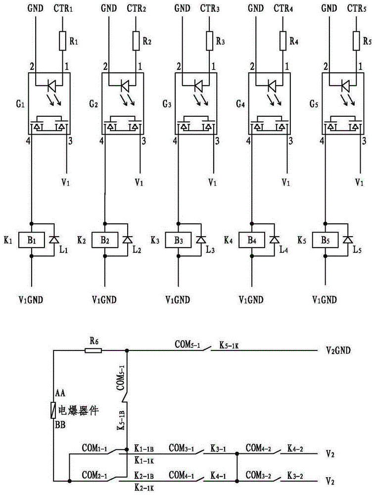
[0031] Such as figure 1 As shown, the ignition circuit in this embodiment includes five electromagnetic relays K 1 、K 2 、K 3 、K 4 and K 5 , five optocoupler relays G 1 , G 2 , G 3 , G 4 and G 5 , five freewheeling diodes L 1 , L 2 , L 3 , L 4 and L 5 , six current-limiting resistors R 1 , R 2 , R 3 , R 4 , R 5 and R 6 .

[0032] For electromagnetic relays, it includes multiple sets of normally open contacts and normally closed contacts, and each common terminal corresponds to a set of normally open contacts and a set of normally closed contacts. Just select the contact and its common terminal.

[0033] Electromagnetic relay K 1 with wire package B 1 , normally open contact K 1-1K and its corresponding public port COM 1-1 , normally closed contact K 1-1B and its corresponding public port COM 1-1 , and the normally open contact K ...


PUM


Abstract

The invention discloses an ignition circuit applied to an electric blasting device, and belongs to the technical field of ignition control. The ignition circuit comprises electromagnetic relays K1-K5, photocoupling relays G1-G5 and current limiting resistors R1-R6; the ignition circuit performs the ignition control through five externally-input control signals CTR1-CTR5, wherein points 1 of G1-G5 are correspondingly connected with CTR1-CTR5 through R1-R6 one to one, points 2 are all grounded, points 3 are all connected with a positive voltage signal V1, and points 4 are correspondingly connected with coils B1-B5 of K1-K5 one to one; a normally open contact K5-1K is connected with a negative voltage signal V2GND; normally closed contacts K5-1B and K1-1B are connected with K2-1B; a common terminal COM5-1 is connected with an end AA of the electric blasting device through R6; an end BB of the electric blasting device is connected with common terminals COM1-1 and COM2-1; a normally open contact K1-1K is connected with a common terminal COM3-1; a normally open contact K2-1K is connected with a common terminal COM4-1; a normally open contact K3-1 is connected with a common terminal COM4-2; a normally open contact K4-1 is connected with a common terminal COM3-2; a common terminal COM4-2 is connected with a common terminal COM3-2; and normally open contacts K4-2 and K3-2 are both connected with a positive voltage signal V2.

Description

technical field [0001] The invention belongs to the technical field of ignition control, in particular to an ignition circuit applied to an electric explosive device. Background technique [0002] With the rapid development of electronic technology, the technical strength and functions of missile-borne equipment are increasing day by day. Electric explosive devices have been widely used in missiles and are in a very important position. Such as the ignition of the rocket engine; the pressurization of the propellant of the liquid engine, the start-up and transfer of the engine; the separation between the missile stages; the detonation of the warhead, etc., all need to use electric explosive devices. Whether the electric explosive device can work safely and reliably has a direct impact on the success or failure of the missile flight, otherwise it will cause serious accidents such as bomb destruction and human death. The application characteristics and conditions of use of elec...

Claims


Application Information

Patent Timeline
Patent Type & Authority Patents(China)
IPC IPC(8): F42D1/045
Inventor 王晓晖纪浩龚俊宇张佳兴韩红业吴胜男
Owner 中国航天科技集团公司第四研究院第四十一研究所
Learn More