
A dynamic ring network topology management method for PCM nodes

A dynamic ring and node technology, applied in the direction of data exchange network, digital transmission system, electrical components, etc., can solve the problems of message looping, network management, and difficult to provide network topology, so as to avoid message looping, improve network management efficiency, Avoid loopback effects

Active Publication Date: 2018-10-16
BEIJING SYMFUN OPTICAL TELECOM TECH DEV
View PDF4 Cites 0 Cited by
  • Summary
  • Abstract
  • Description
  • Claims
  • Application Information

AI Technical Summary

Problems solved by technology

Currently, PCM devices generally support simple chain network, star network and other topological functions, but they cannot provide good support for ring networks, and it is difficult to provide automatic network management functions for other complex network topologies. At the same time, automatic network management of PCM devices requires automatic It is found that the automatic reporting function, in the process of reporting the news, the reported news is easy to form a message loop, forming a network storm, which eventually leads to failure of network management
Another technical difficulty is that during the application process, when some network points experience power failure, failure, or addition or removal of equipment, the original network topology changes, and a new network topology needs to be rediscovered. These automatic adaptations are complicated and easy. As a result, the device cannot be managed by the network, and re-topology routing through the network management still has no effect. It can only be solved by restarting one or more devices. The message loopback has seriously affected the network management.

Method used


Image

  • A dynamic ring network topology management method for PCM nodes

Examples


Embodiment Construction

[0028] The following will clearly and completely describe the technical solution of the present invention in conjunction with the accompanying drawings of the present invention. Obviously, the described embodiments are only some of the embodiments of the present invention, not all of them. Based on the embodiments of the present invention, all other embodiments obtained by persons of ordinary skill in the art without making creative efforts belong to the protection scope of the present invention.

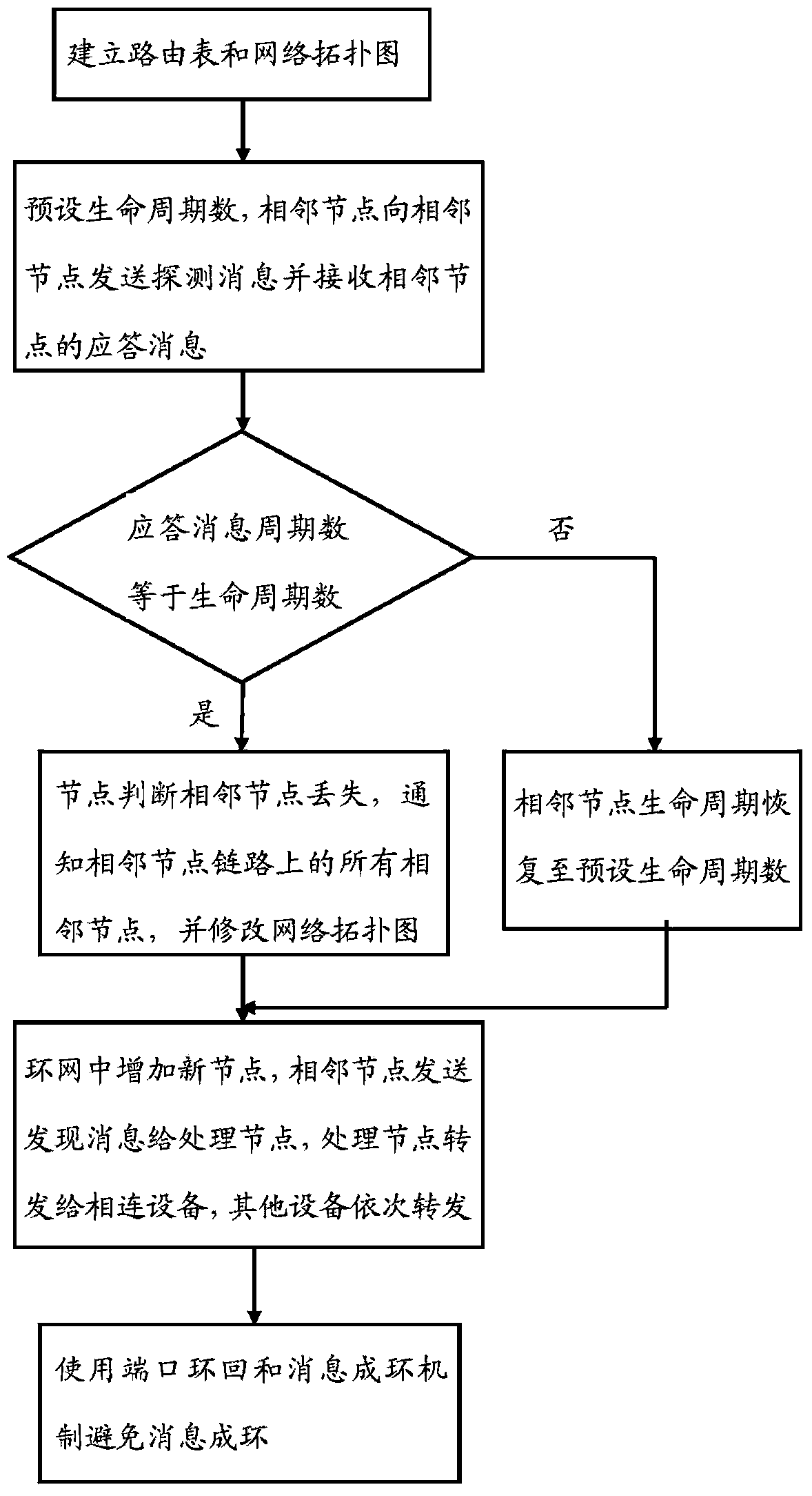
[0029] Such as figure 1 As shown, it is a dynamic ring network topology management method of a PCM node proposed by the embodiment of the present invention, which is characterized in that the method includes the following steps:

[0030] a. Establish the local port routing table, PC routing table and remote port routing table respectively, and establish a network topology diagram in the network management PC according to the routing table. The network topology diagram is a ring netw...


PUM


Abstract

The invention discloses a dynamic ring network topology management method of PCM nodes. The method comprises the following steps: a. Establishing a local port routing table, a PC routing table and a remote port routing table respectively, and establishing a network topology diagram in the network management PC according to the routing table, and the network topology diagram is a ring network topology; b. A node sends a probe message to an adjacent node according to the preset life cycle number, and receives a response message from the adjacent node, and the network management PC judges the node status according to the cycle number of obtaining the response message. In the present invention, the automatic network management of PCM in the dynamic ring network topology is realized, message looping is avoided, the management of access network equipment is greatly facilitated, and the network management efficiency is improved.

Description

technical field [0001] The invention relates to the technical field of PCM ring network topology management, in particular to a dynamic ring network topology management method of PCM nodes. Background technique [0002] Pulse code modulation (PCM, pulse code modulation) is the process of sampling, quantizing and encoding continuously changing analog signals to generate digital signals, which are processed by PCM equipment. [0003] As today's society has higher and higher requirements for informatization and intelligence, equipment network management has become an essential function. PCM equipment has been used from the simplest point-to-point to the current chain network, star network, ring network, and chain belt. Ring, ring-with-chain, ring-with-ring and other forms of network topology applications, from the original no network management or simple network management to the current automatic network management function. Now PCM devices generally support simple chain netw...

Claims


Application Information

Patent Timeline
Patent Type & Authority Patents(China)
IPC IPC(8): H04L12/24H04L12/751H04L45/02
CPCH04L41/12H04L45/02
Inventor 赵文涛孙忠义
Owner BEIJING SYMFUN OPTICAL TELECOM TECH DEV
Learn More