
Method and device for allocating temporary identifiers of cell wireless networks

A wireless network and allocation method technology, applied in wireless communication, network planning, electrical components, etc., can solve problems such as C-RNTI allocation conflicts, and achieve the effect of resolving allocation conflicts

Active Publication Date: 2019-06-25
CHINA MOBILE COMM GRP CO LTD
View PDF6 Cites 0 Cited by
  • Summary
  • Abstract
  • Description
  • Claims
  • Application Information

AI Technical Summary

Problems solved by technology

[0016] The technical problem to be solved by the present invention is to provide a method and device for allocating temporary cell wireless network identifiers, which can solve the problem of C-RNTI allocation conflicts between the master base station and the slave base station

Method used


Image

  • Method and device for allocating temporary identifiers of cell wireless networks
  • Method and device for allocating temporary identifiers of cell wireless networks
  • Method and device for allocating temporary identifiers of cell wireless networks

Examples


Embodiment 1

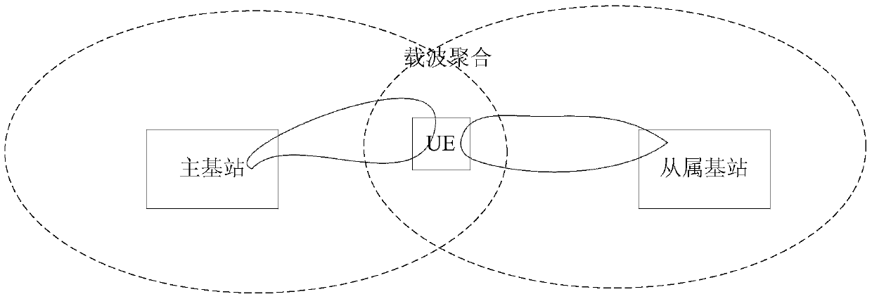
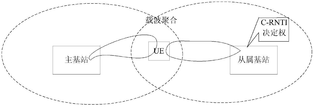
[0088] In this embodiment, the primary base station and the secondary base station transmit user data for the UE at the same time, and the secondary base station determines the C-RNTI allocated to the UE. Specifically, this embodiment can solve the problem of C-RNTI allocation conflict between the master base station and the slave base station through the following implementation solutions.

Embodiment approach 1

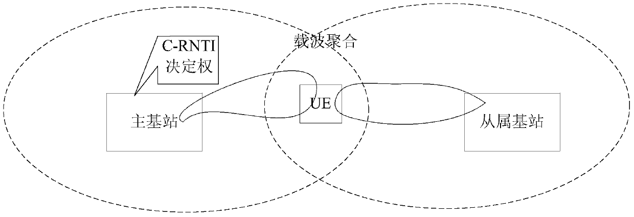
[0089]Embodiment 1: The main base station notifies the base stations within its coverage or overlapping with its coverage (that is, those base stations that may perform dual connection transmission with it) of its real-time C-RNTI allocation status through the inter-base station interface. For example, each base station can use C-RNTIs are all 1-100, and the C-RNTIs 1-50 of the main base station have been occupied, and the C-RNTIs 51-100 are still unallocated, then the main base station can notify the slave base station through the interface with the slave base station The base station itself has used C-RNTI numbers 1-50. For the update of the C-RNTI allocation state information, the master base station can adopt the incremental configuration method. For example, when the No. 51 C-RNTI is used by the master base station, the master base station only needs to notify the slave base station that the No. 51 C-RNTI is used. Update the allocation status of No. 51 C-RNTI from unalloc...

Embodiment approach 2

[0091] Embodiment 2: When the secondary base station needs to allocate a C-RNTI for a UE that is performing dual connection transmission, the secondary base station randomly selects a C-RNTI to allocate to the UE, and then the secondary base station will be The C-RNTI allocated by the UE is sent to the primary base station, and the primary base station will identify the C-RNTI, indicating that the C-RNTI is allocated by the secondary base station, and the primary base station will no longer allocate the C-RNTI to other UEs. Generate an RRC message, and configure the C-RNTI to the UE.


PUM


Abstract

Provided are a cell radio network temporary identifier (C-RNTI) allocation method and apparatus, belonging to the field of wireless communications. The C-RNTI allocation method is applied to a first base station; the first base station can provide service to a user equipment (UE) together with a second base station by means of a double-connection architecture and allocate a C-RNTI to the UE according to the same C-RNTI set. The allocation method comprises: a receiving step, the first base station receiving C-RNTI allocation information of the second base station by means of an inter-base-station interface; a determination step, when the C-RNTI needs to be allocated to the UE collectively served by the first base station and the second base station, the first base station selecting a C-RNTI not used by the first base station and the second base station from the C-RNTI set according to the C-RNTI allocation information of the second base station; and an allocation step, the first base station allocating the C-RNTI to the UE. The present invention can solve the problem of the C-RNTI allocation conflict of a main base station and a slave base station.

Description

technical field [0001] The invention relates to the field of wireless communication, in particular to a method and device for allocating temporary identifiers of cell wireless networks. Background technique [0002] The existing statistical results show that 60% of the mobile voice services and 70% of the data services of mobile operators currently take place indoors; it is predicted that the data services in the future are expected to increase by 1000 times in 10 years, and the indoor data services will account for the total business volume 90% of. Therefore, the bottleneck of traditional cellular network coverage in supporting the development of indoor and hotspot wireless data services has become increasingly prominent, and mobile operators face various challenges in network development: [0003] (1) The wireless access capacity limits of traditional 2G networks and 3G networks are gradually emerging; [0004] (2) It is increasingly difficult to obtain site and antenna ...

Claims


Application Information

Patent Timeline
Patent Type & Authority Patents(China)
IPC IPC(8): H04W16/10
CPCH04W16/10
Inventor 陆扬陈卓江小威
Owner CHINA MOBILE COMM GRP CO LTD
Learn More