Automatic discharging mechanism for roller burnishing of universal joint transmission shaft levers

A universal joint drive shaft and automatic unloading technology, which is applied to conveyor objects, transportation and packaging, roller tables, etc. damage, etc.

Inactive Publication Date: 2016-02-10
WUHU TIANJIN MACHINERY
View PDF6 Cites 3 Cited by
  • Summary
  • Abstract
  • Description
  • Claims
  • Application Information

AI Technical Summary

Problems solved by technology

[0002] The processing process of the universal joint transmission shaft mainly includes rolling, blanking, milling end face and finishing shape. The rolling step is mainly used to eliminate the surface oxide layer of the universal joint transmission shaft blank, and is used for The outer diameter of the joint transmission shaft is quickly rough-machined to improve the work efficiency of the subsequent finish car shape. The automatic unloading mechanism of the universal joint transmission shaft in the prior art mainly includes an axial feed wheel, a radial push The problem with the cylinder and the lateral material holding bracket is that the shaft rod of the universal joint drive is subject to more wear and collision during the unloading process, which is easy to damage the workpiece, which is not conducive to subsequent processing operations and product quality performance

Method used


Image

  • Automatic discharging mechanism for roller burnishing of universal joint transmission shaft levers
  • Automatic discharging mechanism for roller burnishing of universal joint transmission shaft levers

Examples


Embodiment Construction

[0013] The content of the present invention will be described below in conjunction with specific embodiments.

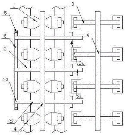
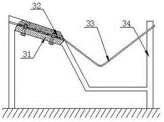
[0014] Such as figure 1 and figure 2 As shown, it is a structural schematic diagram of the automatic unloading mechanism for rolling the universal joint transmission shaft rod according to the present invention. The automatic unloading mechanism of universal joint transmission shaft rod rolling according to the present invention includes: axial feeding wheel 1, radial flip bar 2 and lateral material holding bracket 3, said axial feeding wheel 1 is several and Arranged in line along the conveying direction of the universal joint transmission shaft 4, the axial directions of several axial feeding wheels 1 are horizontal and parallel to each other; The shaft rods 4 are arranged in the same line in the conveying direction, and the several lateral material holders 3 are arranged on one side of the several axial feeding wheels 1; The feeding end 21 and the lifting end ...


PUM


Abstract

The invention discloses an automatic discharging mechanism for roller burnishing of universal joint transmission shaft levers. The automatic discharging mechanism comprises a plurality of axial feeding wheels, radial turnover blocking rods and a plurality of lateral containing supports. The axial feeding wheels are collinearly arranged in the conveying direction of the universal joint transmission shaft levers. The lateral containing supports are collinearly arranged in the conveying direction of the universal joint transmission shaft levers and disposed on one side of the axial feeding wheels. The two ends of each radial turnover blocking rod include a discharging end and a lifting end respectively, and each radial turnover blocking rod further comprises a lifting section and a turnover shaft. Each lifting section is arranged in a gap between the corresponding adjacent axial feeding wheels. Each discharging end is arranged in a gap between the corresponding adjacent lateral containing supports. Each turnover shaft is located between the corresponding lifting section and the corresponding discharging end and is parallel to the axial direction of the universal joint transmission shaft levers. Lifting air cylinders are arranged at the bottoms of the lifting ends.

Description

technical field [0001] The invention relates to an automatic unloading mechanism for universal joint transmission shaft bar rolling and belongs to the technical field of manufacturing constant velocity universal joint products for car drive shafts. Background technique [0002] The processing process of the universal joint transmission shaft mainly includes rolling, blanking, milling end face and finish turning shape. The rolling step is mainly used to eliminate the surface oxide layer of the universal joint transmission shaft blank, and is used for The outer diameter of the joint transmission shaft is quickly rough-machined to improve the work efficiency of the subsequent finishing shape. The automatic unloading mechanism of the universal joint transmission shaft in the prior art mainly includes an axial feed wheel, a radial push The problem of the cylinder and the lateral material holding bracket is that the universal joint transmission shaft is subject to more wear and co...

Claims


Application Information

Patent Timeline
Patent Type & Authority Applications(China)
IPC IPC(8): B65G13/04B65G47/38
Inventor 王键钦
Owner WUHU TIANJIN MACHINERY
Why Eureka
Try Eureka