

Air conditioner
An air-conditioning device and space technology, applied in the direction of mechanical equipment, etc., can solve problems such as slow start, time-consuming, and inability to guide
- Summary
- Abstract
- Description
- Claims
- Application Information
AI Technical Summary
Problems solved by technology
Method used
Image

Examples
Embodiment approach 1
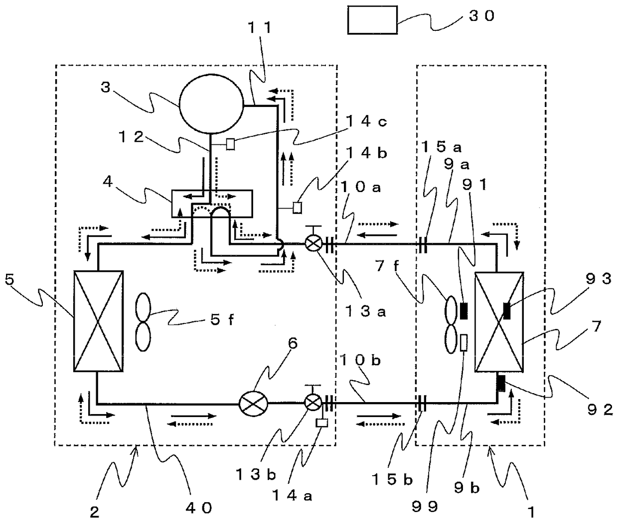
[0050] The air conditioner of Embodiment 1 of this invention is demonstrated. figure 1 It is a refrigerant circuit diagram showing a schematic configuration of the air conditioner of the present embodiment. Additionally, include figure 1 In the following drawings, the dimensional relationship, shape, etc. of each component may be different from the actual ones.
[0051] Such as figure 1 As shown, the air conditioner has a refrigeration cycle 40 that circulates a refrigerant. The refrigeration cycle 40 has a structure in which a compressor 3 , a refrigerant flow switching device 4 , an outdoor heat exchanger 5 (heat source side heat exchanger), a pressure reducing device 6 , and an indoor heat exchanger are sequentially connected via refrigerant piping. 7 (load side heat exchanger) is connected in a ring. In addition, the air conditioner has, for example, an indoor unit 1 installed indoors, and an outdoor unit 2 installed outdoors, for example. The indoor unit 1 and the ou...
Embodiment approach 2
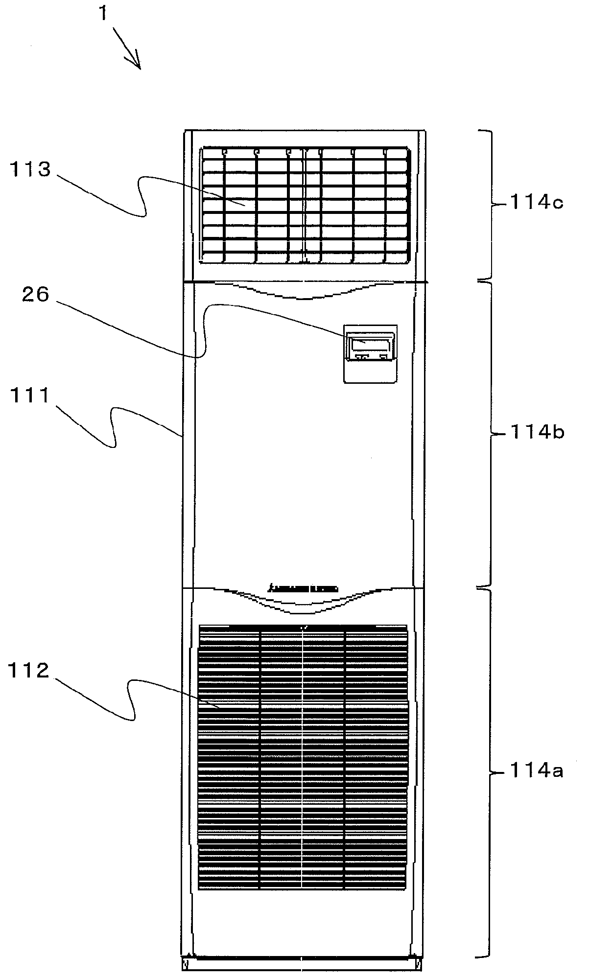
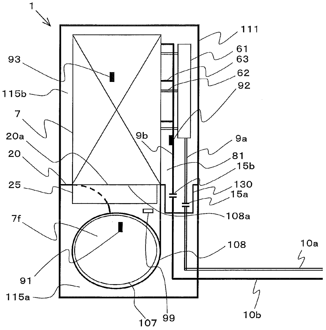
[0097] An air conditioner according to Embodiment 2 of the present invention will be described. Figure 11 It is a front view schematically showing the internal structure of the indoor unit 1 of the air conditioner of this embodiment. Figure 12 It is a side view schematically showing the internal structure of the indoor unit 1 . Components having the same functions and actions as those in Embodiment 1 are assigned the same reference numerals and their descriptions are omitted.
[0098] Such as Figure 11 as well as Figure 12 As shown, the refrigerant detection unit 99 of this embodiment is provided in the space between the suction opening 108b and the suction port 112 in the lower space 115a (that is, outside the fan casing 108 in the lower space 115a). That is, in the present embodiment, the refrigerant detection unit 99 is provided on the downstream side of the indoor blower fan 7f in the outflow path of the leaked refrigerant, as in the second modified example of the f...
Embodiment approach 3
[0105] An air conditioner according to Embodiment 3 of the present invention will be described. Figure 13 It is a front view schematically showing the internal structure of the indoor unit 1 of the air conditioner of this embodiment. Figure 14 It is a side view schematically showing the internal structure of the indoor unit 1 . In addition, components having the same functions and actions as those in Embodiment 1 are denoted by the same reference numerals and their descriptions are omitted.
[0106] Such as Figure 13 as well as Figure 14 As shown, the difference between the indoor unit 1 of this embodiment and the indoor unit 1 of Embodiment 1 is that the partition 20 has a flat plate shape, and image 3 as well as Figure 4 The concave portion 130 shown in FIG. 2 is not formed in the partition portion 20 . However, in this embodiment, like Embodiment 1, joint parts 15a, 15b are arrange|positioned in the upper space 115b. In addition, in Figure 13 as well as Figu...
PUM
 Abstract
Description
Claims
Application Information