Mathematical Image Combination in Scanning Type Microscopy

A microscope and confocal microscope technology, applied in the field of mathematical image combination in scanning microscopes, can solve problems such as signal-to-noise ratio reduction

Active Publication Date: 2018-10-30
FEI CO
View PDF3 Cites 0 Cited by
  • Summary
  • Abstract
  • Description
  • Claims
  • Application Information

AI Technical Summary

Problems solved by technology

To mitigate this effect, one might contemplate reducing the intensity of the radiation beam and / or increasing the scanning speed of the radiation beam, but such measures generally lead to an undesired reduction in the signal-to-noise ratio (SNR)

Method used


Image

  • Mathematical Image Combination in Scanning Type Microscopy
  • Mathematical Image Combination in Scanning Type Microscopy
  • Mathematical Image Combination in Scanning Type Microscopy

Examples


Embodiment 1

[0095] figure 1 is a highly schematic depiction of an embodiment of a scanning type microscope 1 suitable for use in conjunction with the present invention; the depicted microscope is a STEM (i.e. a TEM with scanning capabilities), however, in the context of the present invention, it may only be valid Ground as SEM, confocal microscope, scanning ion microscope, etc. In the drawing, within a vacuum enclosure 2, an electron source 4, such as for example a Schottky gun, generates an electron beam that passes through an electron-optical illuminator 6 for directing / focusing the electron beam onto (substantially flat) specimen S over the selected area. This illuminator 6 has an electro-optical axis 8 and will generally include various electrostatic / magnetic lenses, (scanning) deflectors, correctors (such as astigmatism correction devices), etc.; typically it may also include a condenser system .

[0096] The specimen S is supported on a specimen holder 10, which can be positione...

Embodiment 2

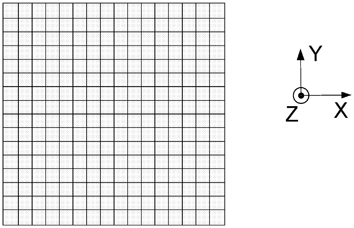
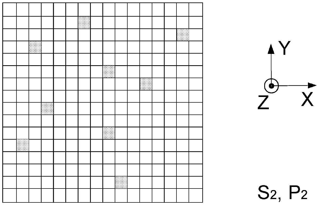
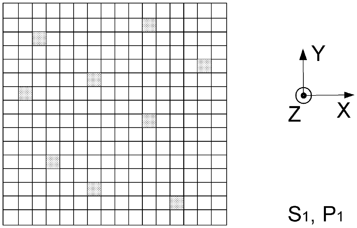
[0102] Figure 2A and 2B Schematically depicts (eg figure 1 Some aspects of traditional methods of image accumulation in scanning-type microscopes of the type depicted in , or an alternative). at this background, Figure 2A Depicts a scanning grid G ​​of the type alluded to above, which is an imaginary mathematical grid / matrix superimposed on (the XY plane of) the specimen S and containing a juxtaposed array of sampling cells (pixels, sampling points) C; As depicted here, the grid G ​​is orthogonal in nature, but this is not limiting and other grid geometries (eg polar) are also conceivable. In conventional scanning microscopy, this entire scanning grid G ​​is "filled" because the scanning beam sequentially observes each cell C in the grid G ​​as the specimen S traces the scan path (i.e. from which data is collected). If a cell C observed (measured) in this way is depicted using shades of gray, this prior art situation is represented in FIG. 2 by the fact that the overal...

Embodiment 3

[0117] As already explained above, the present invention performs a mathematical registration correction to compensate the set {P n} drift mismatch between different members of}. The general principle of such registration correction can be explained in more detail as follows, whereby the term "set" will be used to refer to a cluster D of data points / pixels obtained for imaging purposes. Particularly:

[0118] - When used in the context of Type I methods (see item (I) above and item (A) below), the term refers to the reconstructed subimage I n .

[0119] - When used in the context of Type II methods (see item (II) above and item (B) below), the term refers to the "native" cluster P of sampling points n .

[0120] One can now distinguish the following two situations.

[0121] (A)

[0122] When registering the first collection and the second collection When , a typical alignment algorithm performs the following tasks:

[0123] -Will regarded as right Apply the resu...


PUM


Abstract

A method that uses scanned type microscopy cumulative specimen images, including the following steps: ‑ Provide the specimen described by radiation from the source -oriented radiation in the light;The detector of the radiation flux; ‑ The scanning movement of the beam to withstand the surface of the specimen is used to record the output of the detector as described as a function of the scanning position.Among the first clusters of the sampling point of the sampling point of the sparse distribution of the bidding book; ‑ Repeat this program to accumulate the collection of this cluster {pn} collected during the associated set of the sampling period {Sn}, each one, each of whichThe base of the collection is n> 1; 数 By using the collection {pn} as an input of the comprehensive mathematical reconstruction program to combine the specimen, in which, as the part of the combination process, the mathematical and standard correctionDifferent members of different members.

Description

technical field [0001] The present invention relates to a method of accumulating images of a specimen using a scanning type microscope, comprising the following steps: [0002] - providing a radiation beam directed from a source through an illuminator to irradiate said specimen; [0003] - providing a detector for detecting a radiation flux emanating from said specimen in response to said radiation; [0004] - subjecting the beam to a scanning motion relative to the specimen surface and recording the output of the detector as a function of scanning position. [0005] The invention also relates to a microscope of the scanning type in which such a method can be carried out. Such a microscope can use charged particles to irradiate the specimen (as in the case of e.g. scanning electron microscopes, scanning transmission electron microscopes, scanning ion microscopes and scanning transmission ion microscopes), or it can use photons for this purpose (as in the case of such as in ...

Claims


Application Information

Patent Timeline
Patent Type & Authority Patents(China)
IPC IPC(8): G06T7/00G02B21/00H01J37/22
CPCG02B21/0052H01J37/222G06T2207/10061G02B21/0024G02B21/008H01J37/226H01J37/28H01J2237/226H01J2237/2811G02B21/0048H01J2237/28
Inventor P.波托塞克C.S.库伊曼H.N.斯林格兰德G.N.A.范维恩F.波霍贝
Owner FEI CO
Why Eureka
Try Eureka