
Transmission gear structure

A technology of transmission gears and cam shafts, applied in the directions of instruments, registration/indication, time register, etc., can solve the problem of not allowing errors, and achieve the effect of improving work performance, transmission stability, and reducing external interference.

Inactive Publication Date: 2016-02-10
CHONGQING ALUMINUM KING ALUMINUM CO LTD
View PDF4 Cites 1 Cited by
  • Summary
  • Abstract
  • Description
  • Claims
  • Application Information

AI Technical Summary

Problems solved by technology

[0002] The punch card machine is used to regulate the commuting time of the company's employees. It has been used by most companies. The time is set on the punch card machine. wages, so no mistakes are allowed

Method used


Image

  • Transmission gear structure
  • Transmission gear structure

Examples


Embodiment Construction

[0013] Below in conjunction with accompanying drawing and embodiment

[0014] The present invention is described further:

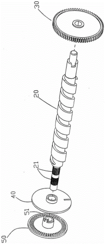
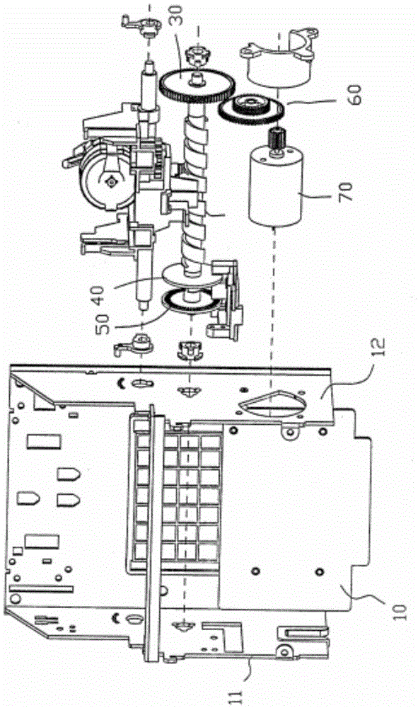
[0015] Such as Figure 1-Figure 2 As shown, a transmission gear structure includes a machine base 10 and a rotating shaft 20, one end of the rotating shaft 20 is set as a connecting rod 21; one end of the rotating shaft 20 is provided with a first transmission gear 30, and the other end of the rotating shaft 20 is provided with a second transmission gear gear 40 and the third transmission gear 50;

[0016] The second transmission gear 40 is provided with a perforation having the same diameter as the connecting rod 21, and the second transmission gear 40 is sheathed on the connecting rod 21 through the perforation; the connecting rod 21 can strengthen the socket and prevent slipping. The connecting rod 21 has a radius of 3 cm.

[0017] The third transmission gear 50 is provided with a protrusion 51, and the protrusion 51 is provided with a limiting cavi...


PUM


Abstract

The invention discloses a transmission gear structure. The transmission gear structure comprises a base and a rotating shaft, wherein a connecting rod is arranged at one end of the rotating shaft; a first transmission gear sleeves the other end of the rotating shaft, and a second transmission gear and a third transmission gear are arranged at the end, with the connecting rod, of the rotating shaft; a penetration hole which is the same as the diameter of the connecting rod in size is formed in the second transmission gear, and the second transmission gear sleeves the connecting rod by the penetration hole; a projection is formed on the third transmission gear, and a limiting cavity which is the same as the diameter of the connecting rod in size is formed in the projection; the third transmission gear is connected with the end surface of the connecting rod through the limiting cavity. The transmission gear structure can reduce outside interferences, is stable in transmission, and improves the working performance of a punched-card machine.

Description

technical field [0001] The invention relates to a gear transmission structure, in particular to the installation of a cam shaft group of a punching machine. Background technique [0002] The punch card machine is used to regulate the commuting time of the company's employees. It has been used by most companies. The time is set on the punch card machine. wages, so no mistakes are allowed. There are multiple gears for transmission in the card punching machine. If the gears are not installed properly, it will directly affect the working performance of the punching card machine. [0003] Therefore those skilled in the art are devoting themselves to developing a kind of punch card machine that improves working performance. Contents of the invention [0004] In view of the above-mentioned defects of the prior art, the technical problem to be solved by the present invention is to provide a card punching machine with improved working performance. [0005] In order to achieve th...

Claims


Application Information

Patent Timeline
Patent Type & Authority Applications(China)
IPC IPC(8): G07C1/10
Inventor 何建国
Owner CHONGQING ALUMINUM KING ALUMINUM CO LTD
Learn More