A capacitor charging method and device with constant power input characteristics

A technology of input characteristics and charging methods, applied in battery circuit devices, circuit devices, collectors, etc., can solve problems such as grid voltage fluctuations, grid oscillations, and reduced grid power supply efficiency

Active Publication Date: 2017-09-26
SOUTHWEST JIAOTONG UNIV
View PDF3 Cites 3 Cited by
  • Summary
  • Abstract
  • Description
  • Claims
  • Application Information

AI Technical Summary

Problems solved by technology

However, the output power of the constant current output power supply gradually increases with the increase of the load capacitor voltage, and the power supply at the input terminal gradually changes, which will cause large current harmonics and reduce the power supply efficiency of the power grid; secondly, the power grid is required to be able to provide power The required peak power will increase the cost of power distribution; finally, after the charging is completed, the power supply will drop from the peak power to 0 instantaneously, which will cause severe fluctuations in the grid voltage, and even cause fluctuations in the grid frequency, especially when the pulse repetition frequency is close to Under the condition of grid frequency operation, it may cause grid oscillation, which will adversely affect the stability and reliability of the grid

Method used


Image

  • A capacitor charging method and device with constant power input characteristics
  • A capacitor charging method and device with constant power input characteristics
  • A capacitor charging method and device with constant power input characteristics

Examples


Embodiment

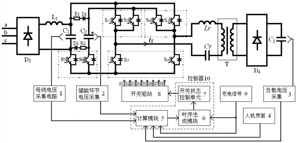
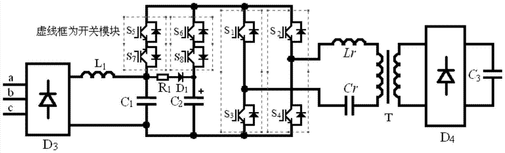
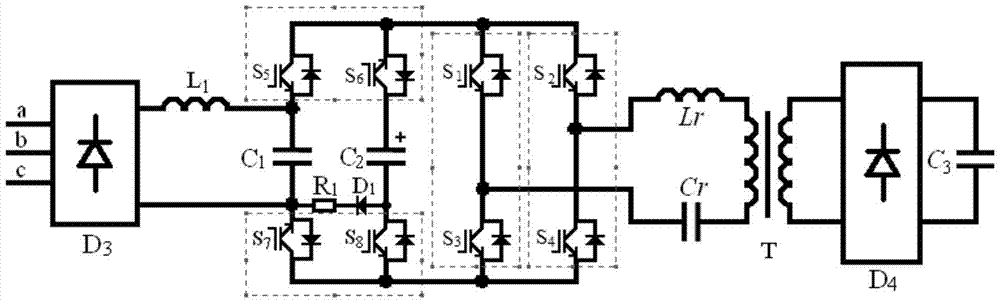
[0102] Taking the control device directly obtained according to the control method of the present invention as an example to further describe the application mode of the present invention, figure 1 , figure 2 and image 3 The essence of the circuit is the same, that is, to increase the temporary energy storage capacitor to participate in the resonance process to achieve constant power at the power supply end. In high-power applications, the use of modules containing multiple switches is more conducive to improving power density, Figure 1 ~ Figure 3 The dotted box in the middle is a 2-switch package module existing in the market. figure 2 The connection relationship of the switch is the simplest; image 3 The more common half-bridge module is used in place of the bidirectional switch module, which can reduce the cost to a certain extent. In addition, the half-bridge module can be used in more grades, which is conducive to the realization of power supplies of different pow...


PUM


Abstract

The technical field of the power supply of the present invention, in particular, relates to a method and device for charging a capacitor with constant power input and constant current output characteristics. The present invention mainly uses the characteristics of the intermittent working mode to transfer the excess energy returned to the temporary energy storage link, so as to realize the charging of the energy storage link while charging the load. The path of the energy storage link to the output energy of the resonant circuit is constructed by means of the excitation source, so that during the charging of the load, the temporary energy storage link plays an auxiliary role in providing power in parallel with the power grid; through the real-time adjustment of the switching time, the constant power supply is realized . Since the temporary energy storage link is a voltage source, and the DC-link’s DC bus is also a voltage source, in order to avoid a short circuit between two voltage sources of different voltages, the two voltage sources are respectively connected in series with a bidirectional switch before connecting to the resonance loop, so that reliable switching of the resonant current between voltage sources can be achieved.

Description

technical field [0001] The invention belongs to the technical field of power supplies, in particular to a capacitor charging method and device with constant power input and constant current output characteristics. Background technique [0002] Pulse power system is used in high power laser and high power microwave and other fields. The capacitor charging power supply is an important part of the pulse power system. With the development of the pulse power system in the direction of high power, high repetition frequency, long running time and high power density, the same requirements are put forward for the charging power supply system. In recent years, with the increase of the power capacity and repetition frequency of the charging system, the adverse impact of the charging power system on the power grid has gradually emerged. For the power grid, the charging power supply is a nonlinear and transient load, which will not only generate a large number of harmonics, but also cau...

Claims


Application Information

Patent Timeline
Patent Type & Authority Patents(China)
IPC IPC(8): H02J7/34H02J3/28H02J3/01
CPCY02E40/40
Inventor 李伟刘庆想张政权
Owner SOUTHWEST JIAOTONG UNIV
Why Eureka
Try Eureka