A hydraulic circuit for active control of prosthetic knee-ankle joint motion

A joint motion and hydraulic circuit technology, applied in fluid pressure actuators, servo motors, servo motor components, etc., can solve problems such as mismatching motion trajectories of amputee patients, and achieve improved battery life, reduced power consumption, and reduced peak power required effect

Active Publication Date: 2020-03-27
BEIHANG UNIV
View PDF5 Cites 0 Cited by
  • Summary
  • Abstract
  • Description
  • Claims
  • Application Information

AI Technical Summary

Problems solved by technology

However, since the passive ankle prosthesis has no power source, there is a problem that the walking of amputee patients does not match the trajectory of normal limb movement. Active ankle prosthesis can effectively solve this problem.

Method used


Image

  • A hydraulic circuit for active control of prosthetic knee-ankle joint motion
  • A hydraulic circuit for active control of prosthetic knee-ankle joint motion
  • A hydraulic circuit for active control of prosthetic knee-ankle joint motion

Examples


Embodiment

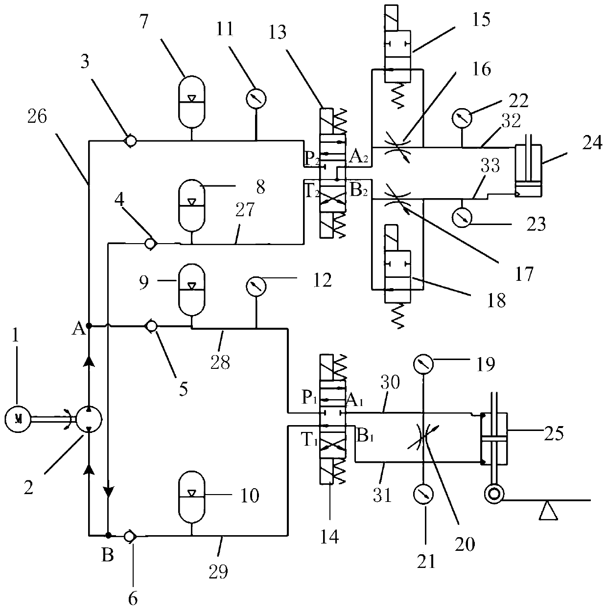
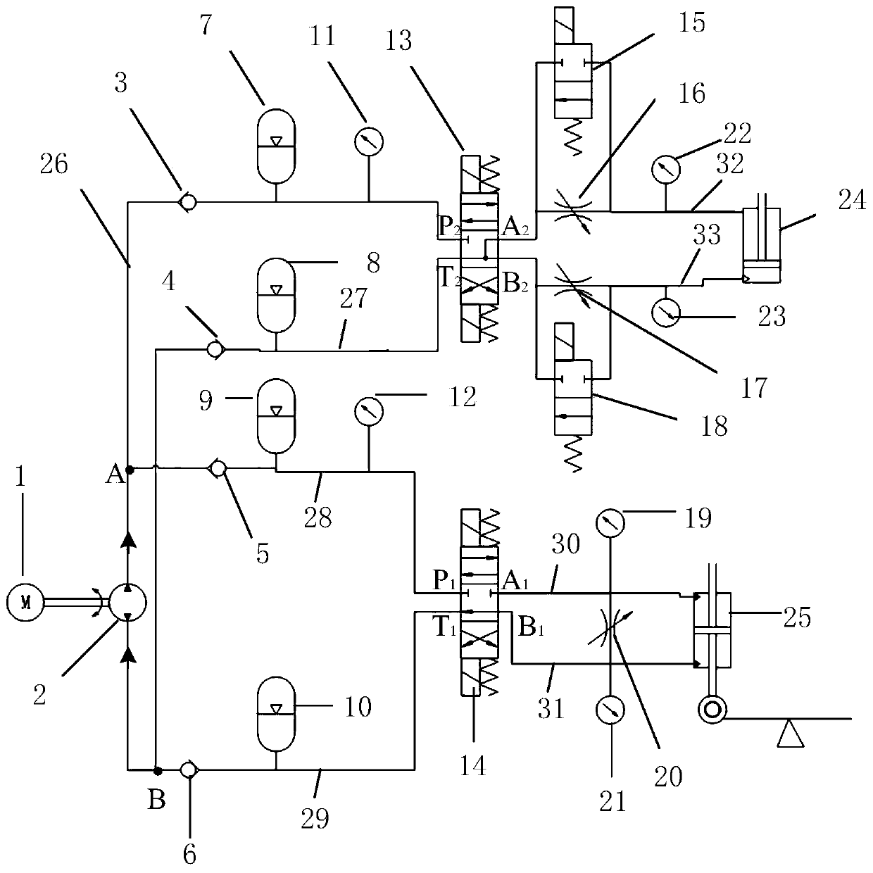
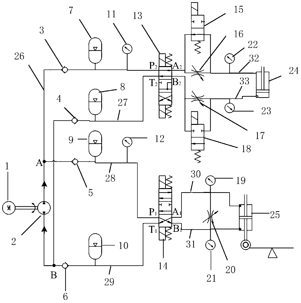
[0039] In the present invention, the hydraulic pump 2 is a plunger hydraulic pump (HYC-MP1F1B / A), the hydraulic pump 2 is controlled by a motor 1 (brushless DC motor 60BLF993000), and the hydraulic circuit is controlled by controlling two three-position four-way valves. Switch between four working states. During the whole process, the electric motor 1 and the hydraulic pump 2 are always in working state, suck oil from the second accumulator 10 through the first one-way valve 5 and the second one-way valve 6, and charge the first accumulator 9 with oil; Oil is sucked from the fourth accumulator 8 through the third check valve 3 and the fourth check valve 4 , and the third accumulator 7 is charged with oil.

[0040] (1) State 1 corresponds to the HS (Heel Strike) process of the human walking cycle, such as figure 1 , for the ankle joint, the first three-position four-way valve 14 is in the neutral position at this time, and the bypass damping valve 20 is connected to the upper ...


PUM


Abstract

The invention discloses a hydraulic circuit capable of actively controlling movement of artificial limb knee and ankle joints, and belongs to the technical field of artificial limbs and orthoses. Thehydraulic circuit specifically comprises an electromotor, a hydraulic pump, a third one-way valve, a fourth one-way valve, a first one-way valve, a second one-way valve, a third energy accumulator, afourth energy accumulator, a first energy accumulator, a second energy accumulator, a second three-position four-way valve, a first three-position four-way valve, a first normally-closed switch valve,a first damper valve, a second damper valve, a second normally-closed switch valve, a bypass damper valve, a single-output-rod hydraulic cylinder, a double-output-rod hydraulic cylinder, a knee jointoil inlet pipeline, a knee joint oil outlet pipeline, an ankle joint oil inlet pipeline, an ankle joint oil outlet pipeline, a first pipeline, a second pipeline, a third pipeline and a fourth pipeline. The hydraulic circuit capable of actively controlling the movement of the artificial limb knee and ankle joints has the characteristics that the power density is large, the output energy is large,the energy can be effectively stored by using the energy accumulators, the buffering capacity can be flexibly controlled by using the damper valves, and the performance of the artificial limbs can beimproved markedly.

Description

technical field [0001] The invention belongs to the technical field of hydraulic control, and relates to a hydraulic control technology for prosthetic limbs and orthoses, in particular, to a hydraulic circuit for actively controlling the motion of a prosthetic limb knee-ankle joint. Background technique [0002] Nowadays, the number of lower extremity amputations is gradually increasing due to traffic accidents, diseases and other reasons. For lower extremity amputees, wheelchairs, crutches and prosthetics are the common ways to compensate for their walking ability deficits. However, the wheelchair occupies a large area, has a limited walking range, and cannot perform stair walking, etc., and requires human assistance. The use of crutches occupies the functions of the hands of a person, and has a great sense of pressure on the user's body. In comparison, wearing a prosthetic limb can compensate for the lack of human body functions, and has advantages in terms of decoration ...

Claims


Application Information

Patent Timeline
Patent Type & Authority Patents(China)
IPC IPC(8): F15B11/08F15B13/02F15B1/02
Inventor 王兴坚张卿张益鑫王少萍杨佳伟
Owner BEIHANG UNIV
Why Eureka
Try Eureka