Transformer substation hoisting device with adjustable hoisting arm

A hoisting device and substation technology, applied in cranes and other directions, can solve the problems of laborious operation and unadjustable boom length, and achieve the effect of strong applicability and manpower saving

Inactive Publication Date: 2016-02-24
CHONGQING XINSHIJIE ELECTRICAL
View PDF8 Cites 3 Cited by
  • Summary
  • Abstract
  • Description
  • Claims
  • Application Information

AI Technical Summary

Problems solved by technology

[0004] In view of the above-mentioned shortcomings of the prior art, the object of the present invention is to provide a substation hoisting device with an adjustable boom, which is used to solve the problems of laborious operation and non-adjustable boom length of the existing hoisting device for substations

Method used


Image

  • Transformer substation hoisting device with adjustable hoisting arm
  • Transformer substation hoisting device with adjustable hoisting arm

Examples


Embodiment 1

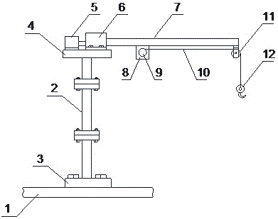
[0018] Such as figure 1 As shown, the present invention provides a hoisting device for a substation with an adjustable boom, which includes a base 1, a support body 2, a telescopic drive mechanism 5, a fixed seat 6, a boom 7, a motor 8, a rotating roller 9, a suspension rope 10, and a fixed pulley 11 and hook 12, the bottom of the support body 2 is set on the base 1, the boom 7 is horizontally set above the support body 2, the top of the support body 2 is provided with a top plate 4, and the telescopic drive mechanism 5 and the fixed seat 6 are fixed on the top plate 4, the fixed seat 6 is provided with a slider, and the telescopic part of the telescopic drive mechanism 5 is connected with the slider; Set on the mounting lug; the motor 8 is fixedly connected to the boom 7, and the output shaft of the motor 8 is connected to the rotating roller 9 through a coupling; one end of the suspension rope 10 is wound on the rotation roller 9, and the other end of the suspension rope 10 ...

Embodiment 2

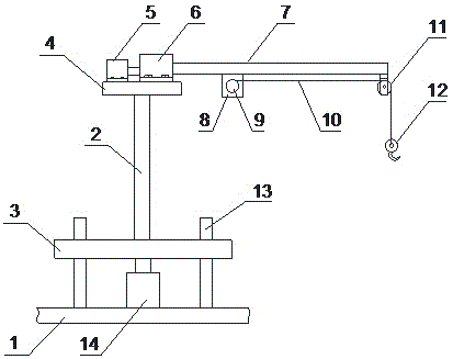
[0024] Such as figure 2 As shown, the structure of this embodiment is basically the same as that of Embodiment 1, the difference is that the support body 2 of this embodiment is a whole, the support base 3 at the bottom of the support body 2 is a square plate structure, and the base 1 is provided with four A guide column 13, the center of the four guide columns 13 is provided with a jack 14, the support base 3 is arranged on the four guide columns 13, and the support base 3 can move up and down along the guide column 13 under the action of the jack 14. This embodiment is different from the lifting method adopted by the support body of embodiment 1. This embodiment uses the jack 14 to realize the lifting of the support body 2, and does not need manual disassembly to increase or decrease the number of segments of the support body 2, so that the operation is more convenient and flexible .


PUM


Abstract

The invention provides a transformer substation hoisting device with an adjustable hoisting arm. The transformer substation hoisting device comprises a base, a support body, a hoisting arm, a telescopic driving mechanism, a fixed base, a motor, a rotation roller, a hoisting rope, a fixed pulley and a hoisting hook, wherein a top plate is arranged at the top of the support body; the telescopic driving mechanism and the fixed base are fixed on the top plate; a sliding block is arranged in the fixed base; a telescopic part of the telescopic driving mechanism is connected with the sliding block; one end of the hoisting arm is connected with the sliding block; a mounting lug is arranged under the other end of the hoisting arm; the fixed pulley is arranged on the mounting lug; the motor is fixedly connected to the hoisting arm; an output shaft of the motor is connected with the rotation roller through a coupler; one end of the hoisting rope is wound on the rotation roller; the other end of the hoisting rope bypasses the fixed pulley and is connected to the hoisting hook. The transformer substation hoisting device with the adjustable hoisting arm has the advantages that on the one hand, the transformer substation hoisting device has no need to pull the hoisting rope manually, so that the manpower is saved; on the other hand, the length of the hoisting arm can be adjusted according to the mounting position of the device without need to repeatedly adjust the mounting position of the whole hoisting device; the transformer substation hoisting device with the adjustable hoisting arm has strong applicability.

Description

technical field [0001] The invention belongs to the technical field of substation maintenance equipment, in particular to a substation hoisting device with an adjustable boom. Background technique [0002] In the substation, with the long-term operation of the equipment and the influence of the outside world, the number of equipment failures and defects is increasing. In order to ensure the reliable operation of the power grid, the work of replacing old equipment has become commonplace. However, both old equipment and new equipment are quite heavy, and the distance between adjacent equipment is narrow. The existing technology adopts the method of crane hoisting and scaffolding for equipment replacement and installation. However, the space of the substation is small, it is difficult for the crane to pass through, and it is time-consuming to build insulating scaffolding. It is laborious and only feasible in substations with large intervals. [0003] For this reason, the inv...

Claims


Application Information

Patent Timeline
Patent Type & Authority Applications(China)
IPC IPC(8): B66C23/04B66C23/14B66C23/16B66C23/62
Inventor 蒋汉贵冯清泉李键黄炼
Owner CHONGQING XINSHIJIE ELECTRICAL
Why Eureka
Try Eureka