Mechanical lifting gripper

A technology of machinery and booms, applied in the field of mechanical lifting grippers, can solve the problems of manpower consumption, material resources, slow work efficiency, etc., and achieve the effect of improved work quality, high work efficiency and reasonable design

Inactive Publication Date: 2014-09-24
SUZHOU TUOKE INSTR EQUIP
View PDF6 Cites 3 Cited by
  • Summary
  • Abstract
  • Description
  • Claims
  • Application Information

AI Technical Summary

Problems solved by technology

In the prior art, when carrying heavy objects in the laboratory, such as high-voltage combined transformers, high-voltage current transformers, and high-voltage voltage transformers, manual handling is usually required, which not only consumes manpower and material resources, but also has very slow work efficiency, usually two people It takes 10 minutes to carry one

Method used


Image

  • Mechanical lifting gripper

Examples


Embodiment Construction

[0013] The present invention is described below in conjunction with accompanying drawing.

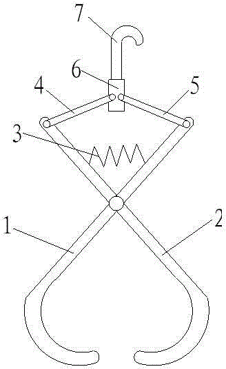
[0014] see figure 1 , a mechanical lifting gripper, including a first lifting arm 1 and a second lifting arm 2, the middle position of the first lifting arm 1 and the second lifting arm 2 is hinged, and the first lifting arm 1 and the second lifting arm The hook part of the arm 2 is in the shape of a half-moon. In actual use, the structural dimensions of the first lifting arm 1 and the second lifting arm 2 are the same. Between the first lifting arm 1 and the second lifting arm 2, a horizontally arranged spring 3 is arranged at the upper end of the hinge, and the spring 3 can keep the first lifting arm 1 and the second lifting arm 2 open when the cargo is not lifted state, the upper end of the first lifting arm 1 is hinged to one end of the first connecting rod 4, the upper end of the second lifting arm 2 is hinged to one end of the second connecting rod 5, and the first connecting rod...


PUM


Abstract

The invention discloses a mechanical lifting gripper which comprises a first lifting arm and a second lifting arm, wherein the middle positions of the first lifting arm and the second lifting arm are articulated, a horizontally arranged spring is arranged at the upper end of the articulated position of the first lifting arm and the second lifting arm; the upper end of the first lifting arm is articulated with one end of a first connecting rod, the upper end of the second lifting arm is articulated with one end of a second connecting rod, the other ends of the first connecting rod and the second connecting rod are articulated with lifting sleeves, and the upper end of each lifting sleeve is provided with a lifting hook. The mechanical lifting gripper disclosed by the invention has the advantages of simple structure, reasonable design, convenient use and high working efficiency, and is capable of lifting a heavy object on the basis of a simple mechanical transmission principle, thereby substituting the traditional manual carrying working method causing time and labor waste. According to the mechanical lifting gripper, the working efficiency and the working quality are greatly enhanced and in the past, one device can be carried by two people together within 10 minutes, but now can be carried within five minutes by only one person.

Description

technical field [0001] The invention relates to the field of machinery, in particular to a mechanical lifting grip. Background technique [0002] The mechanical finger is an automatic operating device that can imitate certain movement functions of the human hand and arm to grab, carry objects or operate tools according to a fixed program. The manipulator is the earliest industrial robot and the first modern robot. It can replace the heavy labor of people to realize the mechanization and automation of production, and can operate in harmful environments to protect personal safety. Therefore, it is widely used in machinery manufacturing, metallurgy, Departments of electronics, light industry and atomic energy. In the prior art, when carrying heavy objects in the laboratory, such as high-voltage combined transformers, high-voltage current transformers, and high-voltage voltage transformers, manual handling is usually required, which not only consumes manpower and material resou...

Claims


Application Information

Patent Timeline
IPC IPC(8): B66C1/28
Inventor 马生芳李建
Owner SUZHOU TUOKE INSTR EQUIP
Why Eureka
Try Eureka