Energy consumer and mechanical switch

A technology of mechanical switches and energy consumers, applied in mechanical equipment, substations/switchgear panels/panels/desks, fluid pressure actuation devices, etc., can solve problems such as closing and bouncing, achieve high maintenance and optimize dynamic performance , Improve the effect of dynamic performance

Inactive Publication Date: 2016-02-24
陈鸽
View PDF8 Cites 3 Cited by
  • Summary
  • Abstract
  • Description
  • Claims
  • Application Information

AI Technical Summary

Problems solved by technology

However, the damping force generated by the energy dissipator will promote the reverse movement of the moving contact, and often cause the moving contact to bounce when closing.

Method used


Image

  • Energy consumer and mechanical switch
  • Energy consumer and mechanical switch
  • Energy consumer and mechanical switch

Examples


Embodiment approach 1

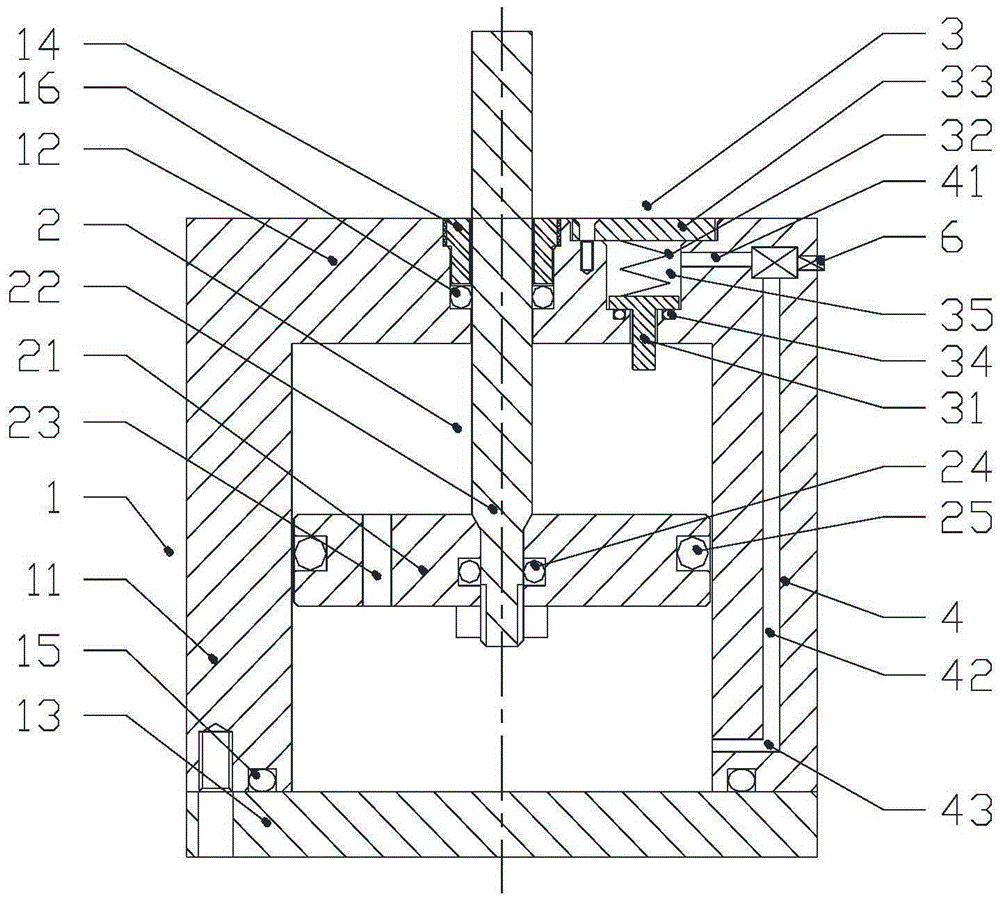
[0036] A kind of energy consumer of the present invention, as figure 1 As shown, it includes a cylinder body 1, a piston mechanism 2, a pressure relief device 3 and a channel 4. The cylinder body 1 includes a first end cover 12, a cylinder barrel 11 and a second end cover 13, the first end cover 12 is sealed and fixed on the top end of the cylinder barrel 1, further, the first end cover 12 and the cylinder The barrel 1 is integrally formed; the second end cover 13 is fixed on the bottom end of the cylinder barrel 1 by bolts, and the second end cover 13 and the bottom end of the cylinder barrel 1 are sealed by the first sealing ring 15 . The piston mechanism 2 includes a piston 21 and a piston rod 22 . The piston 21 is arranged inside the cylinder 1, and the side surface of the piston 21 and the inner surface of the cylinder 11 are sealed by a fourth sealing ring 25, and the piston 21 can move along the axis of the cylinder 1 relative to the cylinder 1. sports. The piston 21...

Embodiment approach 2

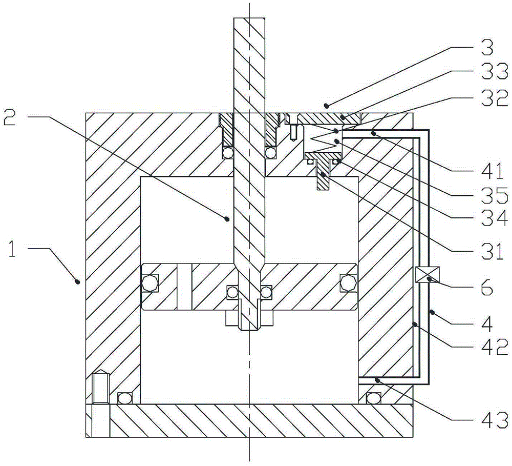
[0041] The difference between Embodiment 2 and Embodiment 1 is only: figure 2 As shown, the channel 4 includes a first channel 41 , a second channel 42 and a third channel 43 . The first passage 41 is built in the first end cover 12 and is in sealing communication with the pressure relief chamber 35, distributed along the radial direction of the first end cover 12; the second passage 42 is arranged outside the cylinder 1, along the cylinder 11 The third channel 43 is arranged in the cylinder wall of the cylinder 11 and is located on the side of the second end cover 13 and is in sealing communication with the second chamber, and is distributed along the radial direction of the cylinder 11 . The first channel 41 , the second channel 42 and the third channel 43 are sequentially connected in a sealed manner, and the regulating valve 6 is arranged on the second channel 42 and communicated with it in a sealed manner.

Embodiment approach 3

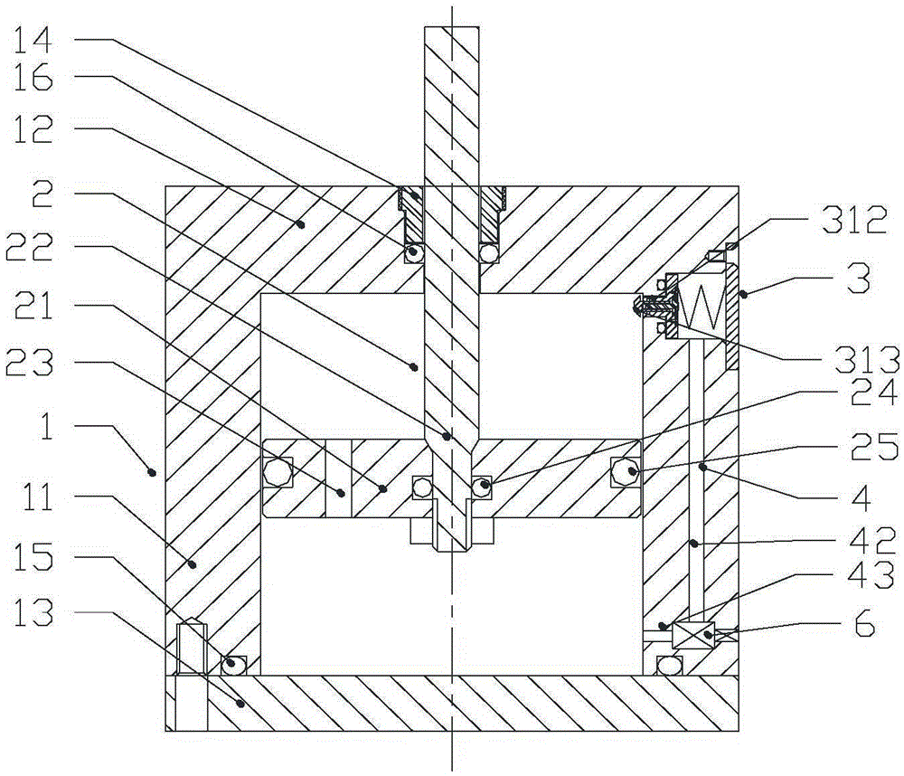
[0043] The difference between Embodiment 3 and Embodiment 1 is only: image 3 As shown, the pressure relief device 3 is assembled on the upper end of the cylinder wall of the cylinder 11 , that is, on the side of the first end cover 12 . The pressure relief chamber 35 of the pressure relief device 3 is arranged on the upper end of the cylinder wall of the cylinder 11, which is composed of a bottom wall and a side wall, and the top opening is opened at the outer end of the cylinder 11. Here, the pressure relief device 3 The direction of the axis determines the top and bottom of the spatial orientation of the pressure relief device 3, and the direction away from the energy consumer is the top. The part of the spool stem 312 of the pressure relief spool 31 that extends into the cylinder body 1 is a spherical crown, and can also be inclined or cam-shaped, so that the side wall of the piston can squeeze the pressure relief spool conveniently, without causing any damage to the press...


PUM


Abstract

The invention discloses an energy consumer and a mechanical switch. The energy consumer comprises a cylinder, a piston, a piston rod, an adjusting valve, a channel and a pressure relieving device, wherein the cylinder comprises a first end cover, a cylinder barrel and a second end cover; the piston rod penetrates through the first end cover, and is fixed together with the piston in the cylinder; the cylinder is divided into a first cavity and a second cavity at the side with the first end cover by the piston; one end part of a pressure relieving valve core positioned in the pressure relieving device assembled on the cylinder extends into the first cavity; the channel is communicated with the pressure relieving device and the second cavity; and the adjusting valve is arranged on the channel. The mechanical switch comprises a single-pole switch and the energy consumer axially connected to each other; when the switch is switched on, the energy consumer relieves the damping at the tail section of the travel thereof, and the switching-on bounce, caused by the damping force, of a moving contact is reduced; the damping relieving strength is adjusted by adjusting the openness of the adjusting valve, so that moving parts of the energy consumer and the mechanical switch are in synergistic effect to optimize the switching-on performance; and the pressure relieving device is arranged on the cylinder of the energy consumer, and is convenient for installation, maintenance and replacement of the pressure relieving valve core.

Description

technical field [0001] The present invention relates to an energy consumer, in particular to an energy consumer with adjustable strength that generates damping at the front end of the stroke and releases damping at the end of the stroke, and a mechanical switch using the energy consumer, which belongs to the switch equipment field. Background technique [0002] At present, new and higher requirements are continuously put forward for the opening and closing performance of high-voltage and low-voltage mechanical switches, and the opening and closing time is required to be shorter without arcing. This will inevitably make the moving contact of the vacuum bubble, which is the core component of the high and low voltage mechanical switch, have a higher speed when opening and closing, and the moving contact will not bounce when closing, and will not discharge and arc. No rebound, no discharge arcing. When the switch is closed, the high-speed moving moving contact of the vacuum bu...

Claims


Application Information

Patent Timeline
Patent Type & Authority Applications(China)
IPC IPC(8): F15B13/02H02B1/04
CPCF15B13/02H02B1/04
Inventor 陈鸽
Owner 陈鸽
Why Eureka
Try Eureka