
Parallel flow heat exchanger, air conditioner with the same and control method of air conditioner

A technology of parallel flow heat exchanger and air conditioner, which is applied in the direction of indirect heat exchanger, heat exchanger type, refrigerator, etc., can solve the problems of difficult frost removal, limited effect, and long time consumption, so as to speed up the defrosting speed, The effect of obvious effect and simple design structure

Active Publication Date: 2016-02-24
GD MIDEA AIR-CONDITIONING EQUIP CO LTD +1
View PDF8 Cites 4 Cited by
  • Summary
  • Abstract
  • Description
  • Claims
  • Application Information

AI Technical Summary

Problems solved by technology

Due to the better heat transfer performance of the parallel flow heat exchanger, this is more obvious. When the refrigerant reaches the inlet of the cooling flow path (that is, the inlet of the first process) during defrosting, the temperature of the refrigerant can reach about 80°C, and after the first After the process, the temperature may be only about 50°C when it reaches the header on the other side, so the frost at the end of the second process, which is near the outlet of the cooling flow path, is the most difficult to remove and takes the longest time.
Although the high-temperature refrigerant in the lowermost flat tubes in the first process can help melt the frost layer on the uppermost two to three flat tubes of the second process through heat conduction, the second process generally has eight to twelve flat tubes, Therefore, the effect of this "help" is very limited, and it is only effective for the upper part of the second process, but it is powerless for the lower part

Method used


Image

  • Parallel flow heat exchanger, air conditioner with the same and control method of air conditioner
  • Parallel flow heat exchanger, air conditioner with the same and control method of air conditioner
  • Parallel flow heat exchanger, air conditioner with the same and control method of air conditioner

Examples


Embodiment Construction

[0042] The principles and features of the present invention are described below in conjunction with the accompanying drawings, and the examples given are only used to explain the present invention, and are not intended to limit the scope of the present invention.

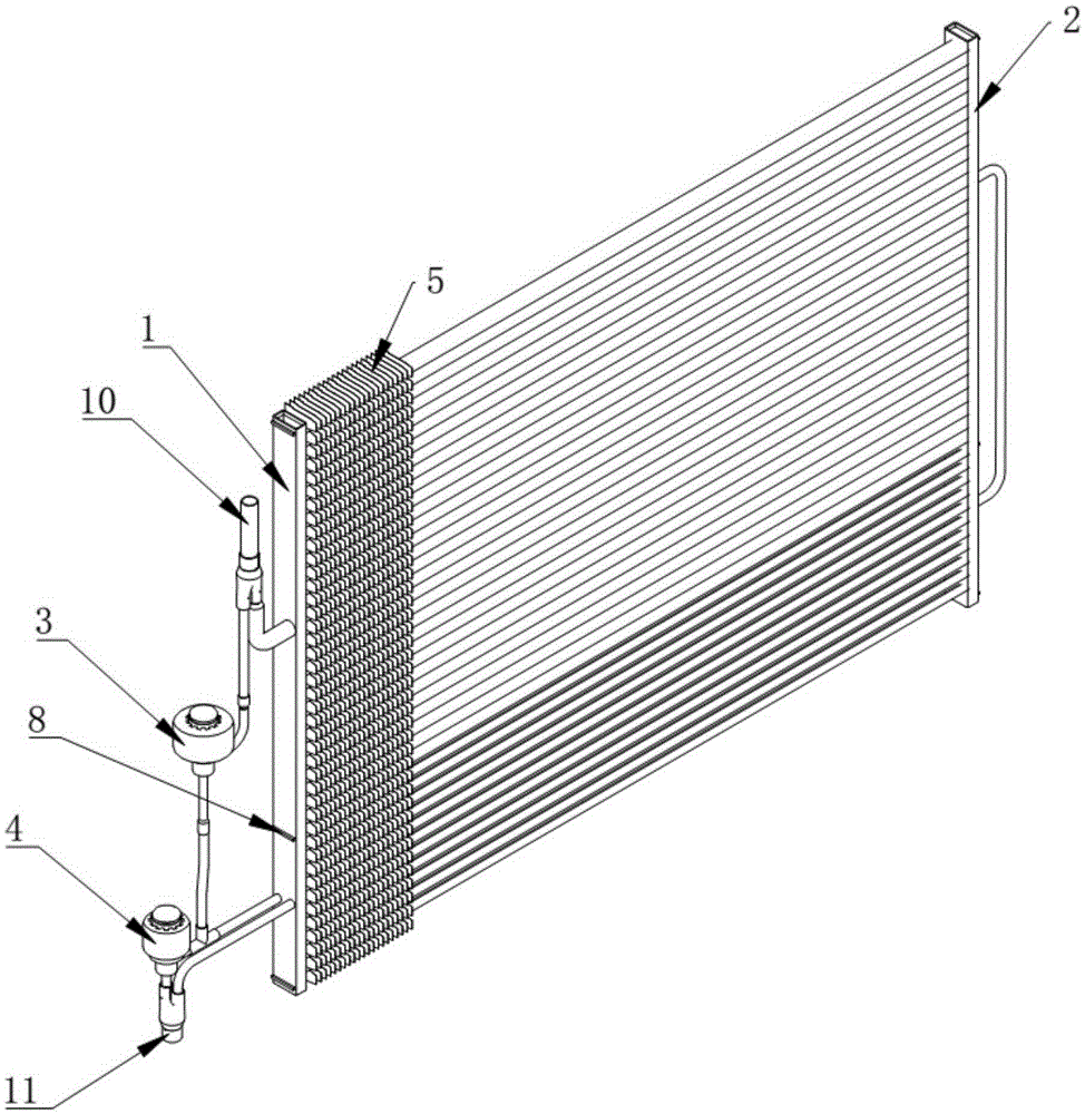
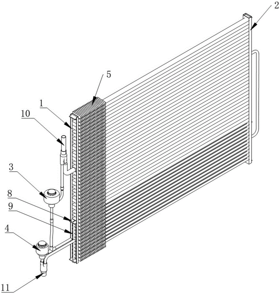
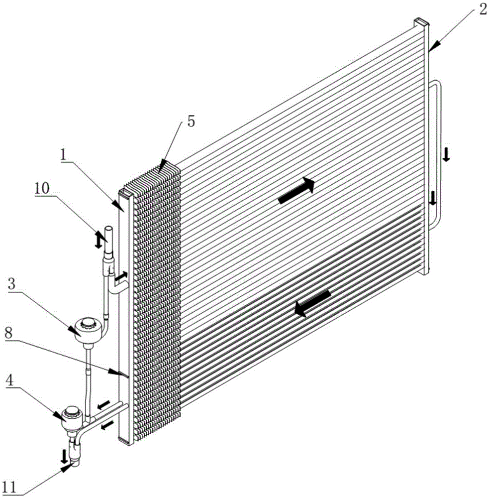
[0043] Such as figure 1 , figure 2 As shown, a parallel flow heat exchanger includes a first header 1 and a second header 2 arranged vertically side by side and a plurality of horizontally arranged flat tubes, and the two ends of the plurality of flat tubes are connected respectively The first header 1 and the second header 2, a plurality of flat tubes are also inserted with a plurality of fins 5 laterally, and the first header 1 is externally connected with a first interface 10 and a second The interface 11 also includes a transverse partition 8 and a vertical partition 9, the transverse partition 8 is arranged laterally in the middle between the first header 1 and the second header 2, and connects a plurality of...


PUM


Abstract

The invention relates to a parallel flow heat exchanger, an air conditioner with the same and a control method of the air conditioner. Two sets of flat tubes are pressed in fin clamping grooves of a lower heat exchange unit of the parallel flow heat exchanger respectively to form two sets of independent circulating channels. When the air conditioner is in a defrosting state through reversing of a four-way valve, a first electromagnetic valve is powered on to be opened while a second electromagnetic valve is closed, and one part of high-temperature refrigerant coming out of a compressor passes through the first electromagnetic valve and a left collecting rube to directly enter the first flat tube channel in the lower heat exchange unit, is converged with refrigerant flowing from a second collecting tube and an upper heat exchange unit after a heat exchange process and then returns from the second flat tube channel. The defrosting speed of the lower heat exchange unit is increased, the defrosting time is shortened, and then the low-temperature heating capacity of a whole air conditioner system is improved. The design structure is simple, the effect is remarkable, and implementation is convenient.

Description

technical field [0001] The invention relates to a parallel flow heat exchanger, an air conditioner containing the same and a control method for the air conditioner, and belongs to the technical field of air conditioner heat exchangers. Background technique [0002] Parallel flow heat exchanger is a kind of all-aluminum heat exchanger, and it has high heat exchange efficiency, compact structure, and cost is more advantageous than ordinary copper tube heat exchanger, and it is more and more valued by various air-conditioning manufacturers. When the parallel flow heat exchanger is used as the outdoor heat exchanger of the cooling and heating machine, there is a more obvious disadvantage, that is, the performance at low temperature is poor, and the heat transfer capacity is not as good as that of the copper tube heat exchanger of the same specification. Analyzing the reason, it is mainly because the frosting speed of the parallel flow heat exchanger is faster than that of the co...

Claims


Application Information

Patent Timeline
IPC IPC(8): F28D1/04F25B47/02
CPCF25B47/02F28D1/0417
Inventor 罗羽钊汪先送
Owner GD MIDEA AIR-CONDITIONING EQUIP CO LTD
Learn More