
Multi-node channel scanning and distribution method in wireless network

A channel scanning and wireless network technology, applied in the field of wireless communication, to achieve the effect of improving system throughput, improving transmission performance and improving efficiency

Inactive Publication Date: 2016-02-24
SOUTHWEST JIAOTONG UNIV
View PDF8 Cites 27 Cited by
  • Summary
  • Abstract
  • Description
  • Claims
  • Application Information

AI Technical Summary

Problems solved by technology

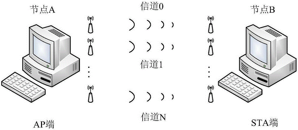
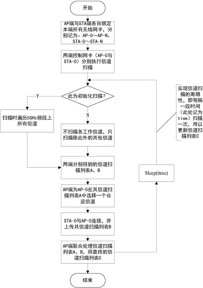
[0015] A multi-node channel scanning and allocation method in a wireless network, which is used to solve the periodicity of multi-node association when multiple wireless network cards on the same node are bound for joint transmission in a wireless network, especially in an IEEE802.11n / ac wireless local area network WLAN Channel scanning problem and unified channel allocation to realize adaptive selection of channels with different bandwidths and non-adjacent quality; use 5GHz frequency band WLAN as the backhaul channel, and backhaul end nodes are equipped with multiple wireless network cards at the same time, and each node is selected One of the multiple wireless network cards on the network is used as the control network card to perform the channel scanning function, and the other wireless network cards are used as data network cards to complete the data transmission process. Taking two nodes A and B as an example, the specific process include:

Method used


Image

  • Multi-node channel scanning and distribution method in wireless network
  • Multi-node channel scanning and distribution method in wireless network
  • Multi-node channel scanning and distribution method in wireless network

Examples


Embodiment Construction

[0045] In order to make the purpose, technical solution and advantages of the present invention clearer, the present invention will be further described below in conjunction with the accompanying drawings. The specific embodiments described here are only used to explain the present invention, not to limit the present invention.

[0046] The following uses IEEE802.11nWLAN as an example to explain the multi-node channel scanning and allocation method and system proposed in the present invention. For the convenience and clarity of describing the content of the present invention, two nodes (node ​​A, node B) are used as examples for illustration, such as figure 1 shown. Nodes A and B are respectively regarded as the AP end and the STA end, and each of them is bound with (N+1) wireless network cards, one of which is used as a control network card, and the rest are used as data network cards. The control network card is mainly used to realize periodic channel scanning; the data ne...


PUM


Abstract

The invention discloses a multi-node channel scanning and distribution method in a wireless network. The multi-node channel scanning and distribution method in a wireless network is used for multi-node united channel scanning and unified channel distribution during the united transmission process when a plurality of wireless local area network cards are bound at the same node in a wireless network, especially an IEEE 802.11n / ac wireless local area network (WLAN) so as to realize adaptive selection of nonadjacent channels with different bandwidth and higher quality. The method utilizes a 5GHz frequency range WLAN as a return channel, and comprises an initialization channel scanning process and a periodicity channel scanning process, wherein the initialization channel scanning process traverses all the channels on the 5GHz frequency range; the periodicity channel scanning process only needs to scan a work channel where each wireless local area network card is; therefore, the scanning time is saved and negative influence on all the work channels is avoided; and at the same time each node utilizes multi channels to transmit data unitedly, so that the transmission bandwidth is expanded and the throughput of system is improved and the method can overcome the defect that the channel quality of part of frequency range is low so as to cause the overall performance of the system is reduced as a single continuous aggregation channel is used to transmit data.

Description

technical field [0001] The present invention relates to the field of wireless communication. The wireless network, in addition to IEEE802.11n / ac wireless local area network (WLAN), includes wireless heterogeneous network, wireless sensor network, wireless personal area network access or bandwidth aggregation of return transmission Both apply. Background technique [0002] In order to meet the growing demand for wireless services, wireless networks, especially IEEE802.11WLAN, as a supplement to cellular mobile communication systems, are gradually becoming an integral part of future mobile communication systems. [0003] We all know that before using any network, one must first find out its existence. In the field of wireless communication, the process for a mobile station (STA) to identify an existing network in its area is called scanning, and there are two main forms: passive scanning and active scanning. Passive scanning is to determine the existence of surrounding APs b...

Claims


Application Information

Patent Timeline
IPC IPC(8): H04W24/10H04W48/16H04W84/12
CPCH04W24/10H04W48/16H04W84/12
Inventor 薛青方旭明倪克顺张凯李鸿斌刘宏源陈琳王轶欧凌扬珺
Owner SOUTHWEST JIAOTONG UNIV
Learn More