A two-stage lateral transmission three-roll rolling mill

A three-roll mill, drive-side technology, applied in metal rolling stands, metal rolling mill stands, driving devices for metal rolling mills, etc., can solve the problem that the three-roll mill roll gap cannot be adjusted, increase energy consumption, increase backup Rack etc.

Active Publication Date: 2018-08-07
BEIJING WANTAI MACHINERY EQUIP
View PDF7 Cites 8 Cited by
  • Summary
  • Abstract
  • Description
  • Claims
  • Application Information

AI Technical Summary

Problems solved by technology

[0002] The three-roll 120° rolling mill was applied to the reduction and sizing unit of rods and wires in 1954. The roll gap of the early three-roll mill could not be adjusted, so the number of spare stands needed to be increased
Until 1984, KOCKS launched the RSB reducing and sizing unit. The frame at the center of the C-type module uses three eccentric sleeves inside to drive the rolls to make eccentric movements to adjust the roll gap. The power of the frame depends on the three-way input of the C-type module. Although this kind of rolling mill can adjust the roll gap, the cost is to increase the bulky C-shaped module, which not only increases the burden on equipment investment, but also reduces the efficiency of the equipment due to the extension of the transmission chain, and excessively increases the energy consumption. consume

Method used


Image

  • A two-stage lateral transmission three-roll rolling mill
  • A two-stage lateral transmission three-roll rolling mill
  • A two-stage lateral transmission three-roll rolling mill

Examples


Embodiment Construction

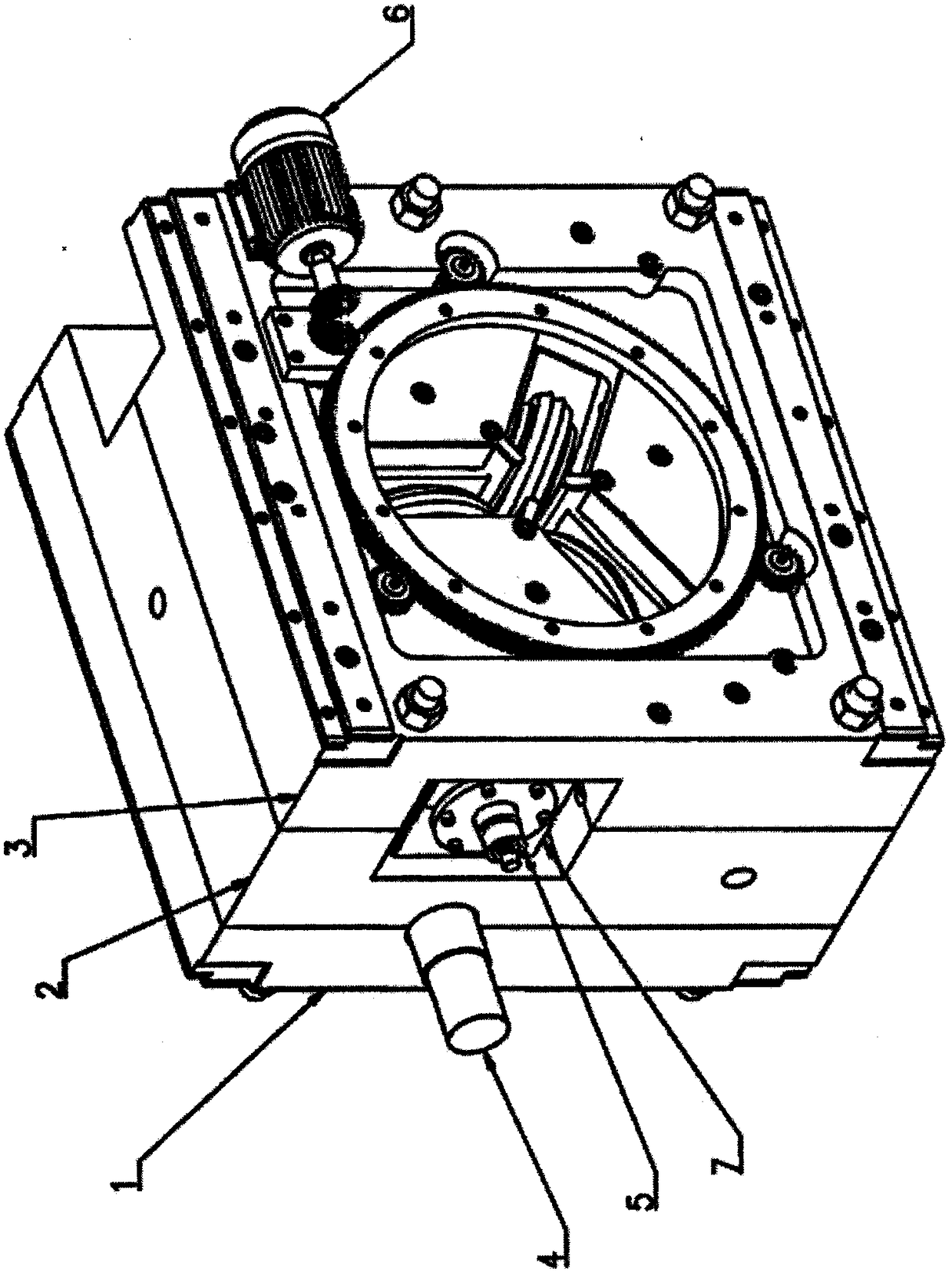
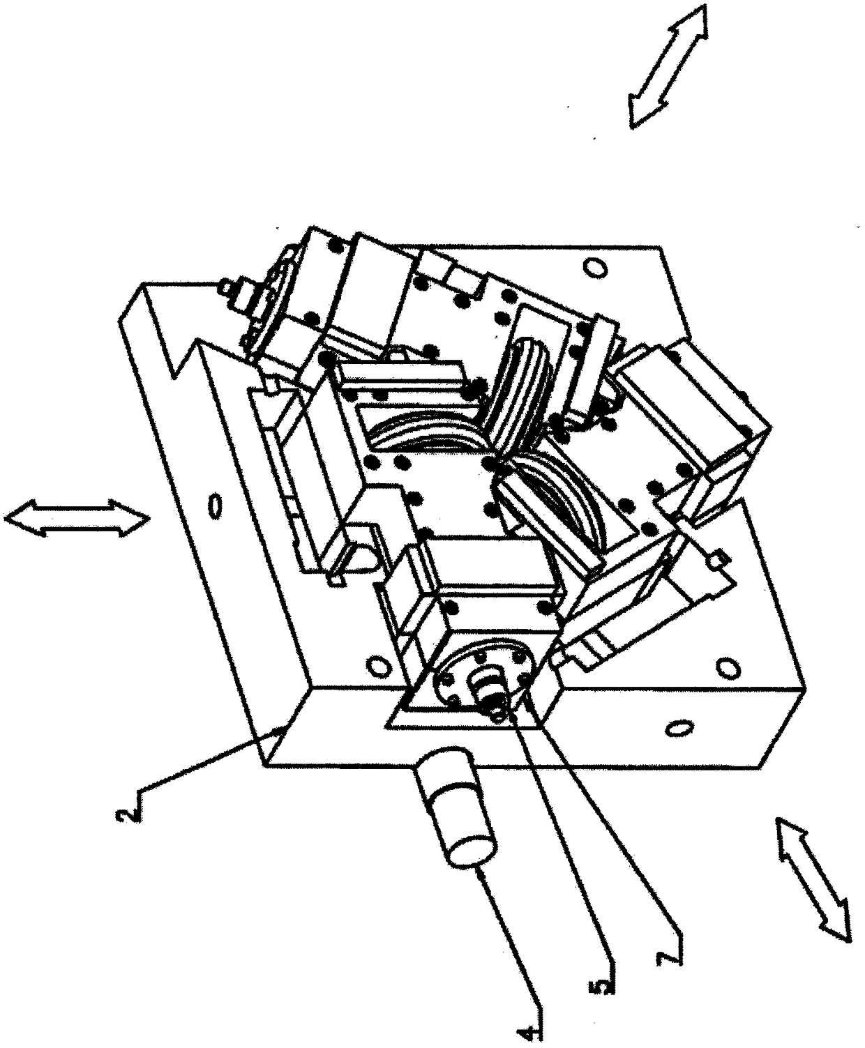
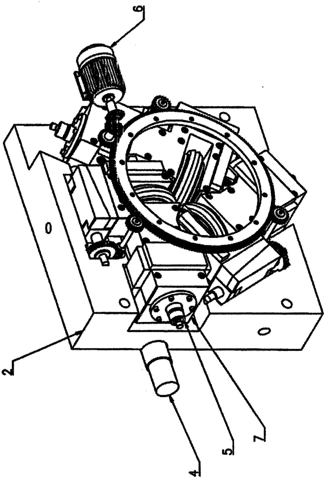
[0019] The core of the present invention is to move the rolls perpendicular to the direction connecting the centers of the two transmission gears to adjust the roll gap, and in order to cooperate with this way of adjusting the roll gap, three roll chocks 7 that are designed and arranged to move perpendicular to the rolled piece, and Gap adjustment mechanism 6. Embodiments of the present invention are as Figure 7 As shown in middle a, when adjusting the roll gap, the roll 5 is perpendicular to the line connecting the center of the drive shaft 4, and moves a certain distance within the roll gap adjustment range, deviated from the line connecting the centers of the original two meshing gears, the gear of the roll 5 is in the new A new connection line is formed between the center point and the gear center of the transmission shaft 4. This connection line forms a right-angled triangle with the line connecting the original center line and the distance that the adjustment roll gap m...


PUM


Abstract

The invention belongs to the technical field of mechanical engineering and relates to a two-stage lateral transmission three-roll rolling mill. The system includes: machine base transmission side cover, machine base, machine base roll side cover, transmission shaft, roll, roll gap adjustment mechanism, roll bearing seat. The present invention is a three-roll rolling mill with two-stage lateral input transmission power. When the roll gap is adjusted, the rolls are perpendicular to the line connecting the center of the transmission shaft gear and the center of the roll gear. After the roll gap is adjusted, the difference between the center moments of the two gears within the allowable tolerance range of the central moment. Three roll chocks that move vertically to the rolled piece and the roll gap adjustment mechanism are designed and arranged in conjunction with the roll gap adjustment method. The roll gap adjustment mechanism synchronously drives the wedge to move to increase or decrease the roll gap. The invention inputs transmission power on the sides of the three rollers, cancels the C-shaped module, simplifies the power input of the rolling mill, and reduces equipment weight and energy consumption.

Description

field of invention [0001] The invention belongs to the technical field of mechanical engineering and relates to a two-stage lateral transmission three-roll rolling mill. It is suitable for the rolling of metal plates, wires, and pipes, and also for the low-temperature temperature-controlled rolling of metals. Background technique [0002] The three-roll 120° rolling mill was applied to the reduction and sizing unit of rods and wires in 1954. The roll gap of the early three-roll mill could not be adjusted, so the number of spare stands needed to be increased. Until 1984, KOCKS launched the RSB reducing and sizing unit. The frame at the center of the C-type module uses three eccentric sleeves inside to drive the rolls to make eccentric movements to adjust the roll gap. The power of the frame depends on the three-way input of the C-type module. Although this kind of rolling mill can adjust the roll gap, the cost is to increase the bulky C-shaped module, which not only increase...

Claims


Application Information

Patent Timeline
Patent Type & Authority Patents(China)
IPC IPC(8): B21B35/12B21B31/20B21B31/07B21B13/10
Inventor 胡诗国寇晓春
Owner BEIJING WANTAI MACHINERY EQUIP
Why Eureka
Try Eureka