Fan hub balancing structure

A technology of balancing structure and fan wheel, which is applied to components of pumping devices for elastic fluids, non-variable-capacity pumps, machines/engines, etc., can solve the overall strength effect of the top 11, the deformation of the sides, and the side 12. And other issues

Inactive Publication Date: 2016-03-02
ASIA VITAL COMPONENTS SHENZHEN CO LTD
View PDF5 Cites 2 Cited by
  • Summary
  • Abstract
  • Description
  • Claims
  • Application Information

AI Technical Summary

Problems solved by technology

Although the punching method in the prior art can improve the unbalance of the metal hub 1, another problem arises, that is, because the center of the top 11 of the existing metal hub 1 has an opening 111 for inserting an axis, And a groove 113 is provided adjacent to the periphery of the opening 111, so when the metal hub 1 is balanced and the top 11 is punched and removed, the overall strength of the top 11 will be affected by the influence of the groove 113
[0005] In addition, because the current stamping die is designed for the upper and lower dies, the surface of the side portion 12 of the metal hub 1 cannot be punched to improve the unbalance of the metal hub 1; if the side portion 12 of the metal hub 1 is turned 90 degrees, When the one peripheral surface and the other peripheral surface of the side portion 12 are respectively opposed to the upper punch and the lower punch of the stamping die, there is no inner surface of the one peripheral surface and the other peripheral surface of the punched hole respectively. Another support is used to support it, so that after the peripheral surface of the side part 12 is punched by the upper die, the side part 12 of the metal hub 1 will be severely deformed or punched. The magnet contained in the metal hub 1 is scratched or shaped by punching burrs

Method used


Image

  • Fan hub balancing structure
  • Fan hub balancing structure
  • Fan hub balancing structure

Examples


Embodiment Construction

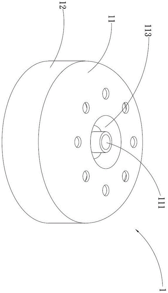
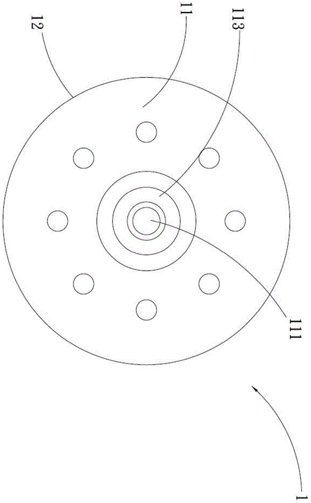
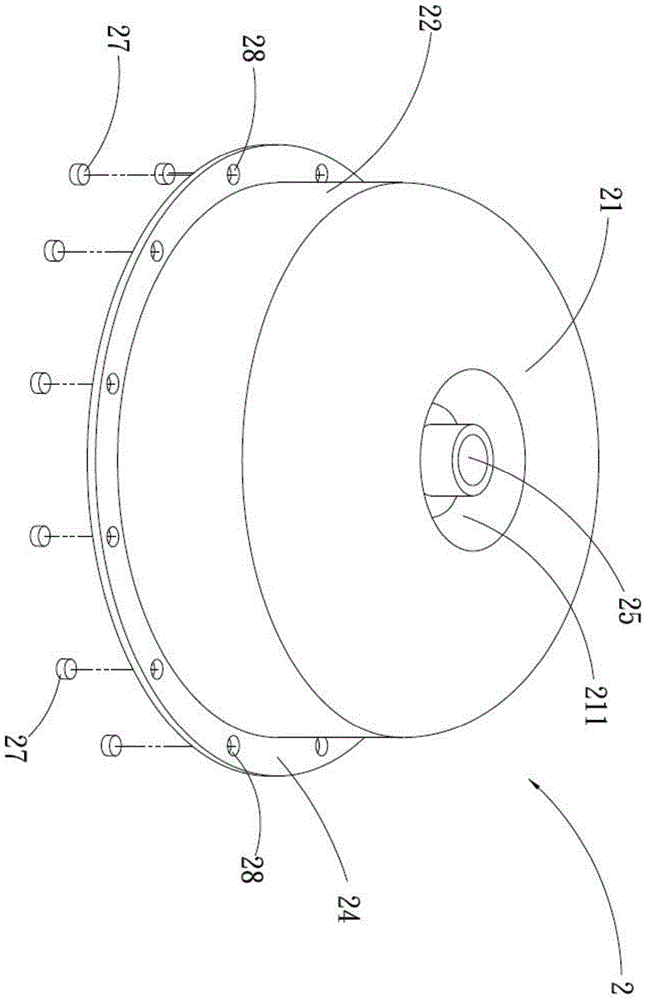
[0053] The present invention provides a fan hub balance structure, please refer to figure 2 , 3 , is a perspective view and a top view schematic diagram of the first preferred embodiment of the present invention, supplemented by referring to Figure 4 As shown; the fan hub balance structure includes a hub body 2, the hub body 2 is made of metal material (such as iron, aluminum), and the hub body 2 has a top 21, a side portion 22, a lip 24 and An opening 25, the opening 25 is opened at the center of the top 21, and it is used for inserting an axis 33, that is, one end of the axis 33 is plugged into the opening 25, and the other end is accommodated. In an accommodating space 26 of the hub body 2, the side portion 22 is provided with an upper end 221 and a lower end 222. It is formed by bending toward the outer side of the side portion 22 .

[0054] The above-mentioned upper end 221 is connected to the peripheral edge of the top 21, and the lower end 222 is connected to an en...


PUM


Abstract

The invention provides a fan hub balancing structure which comprises a hub body. The hub body is provided with a top, a side portion extending outwards from the periphery of the top and a lip portion. The lip portion is connected with the lower end of the side portion and provided with at least one unnecessary weight portion. The unnecessary weight portions are located on the lip portion and balance portions are formed on the lip portion after the unnecessary weight portions are removed. The fan hub balancing structure has the beneficial effects that the balance effect is achieved for hub body, and construction is convenient.

Description

technical field [0001] The invention relates to a fan hub balance structure, in particular to a fan hub balance structure which uses punching or hole punching to remove redundant weight parts on the hub so that the hub can achieve balance. Background technique [0002] Generally, the materials used for the hubs of computer fans can be roughly divided into two types of hubs: metal and plastic. In the current fan production process, in order to achieve the best balance when the fan is running, so as to reduce unnecessary vibration, such as To deal with a defective product with the "Reduce-to-Balance" balance method, it is necessary to reduce the weight of the overweight part of the hub. The metal (such as iron material) hub is used as an illustration. Because the general metal hub is stamped and formed by a mold, and the metal hub cannot reach a relatively uniform thickness when stamping and stretching, so the weight of the formed metal hub will be inconsistent. , so as to ca...

Claims


Application Information

Patent Timeline
Patent Type & Authority Applications(China)
IPC IPC(8): F04D29/32F04D29/66
Inventor 黄俊豪何俊良
Owner ASIA VITAL COMPONENTS SHENZHEN CO LTD
Why Eureka
Try Eureka