Column-type gas recognition device
An identification device and gas technology, applied in the field of life, can solve problems such as deflagration accidents, incomplete gas, non-combustion, etc., to avoid personal safety accidents and realize the effect of automatic identification
- Summary
- Abstract
- Description
- Claims
- Application Information
AI Technical Summary
Problems solved by technology
Method used
Image

Examples
Embodiment 1
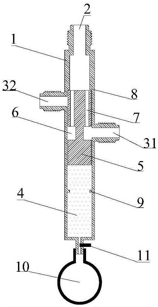
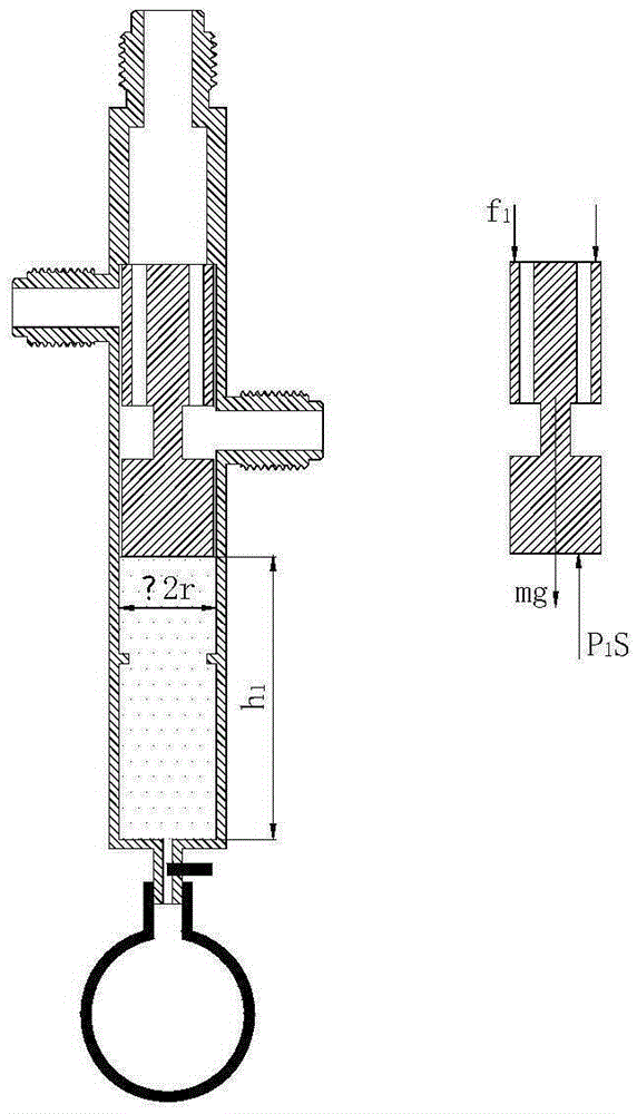
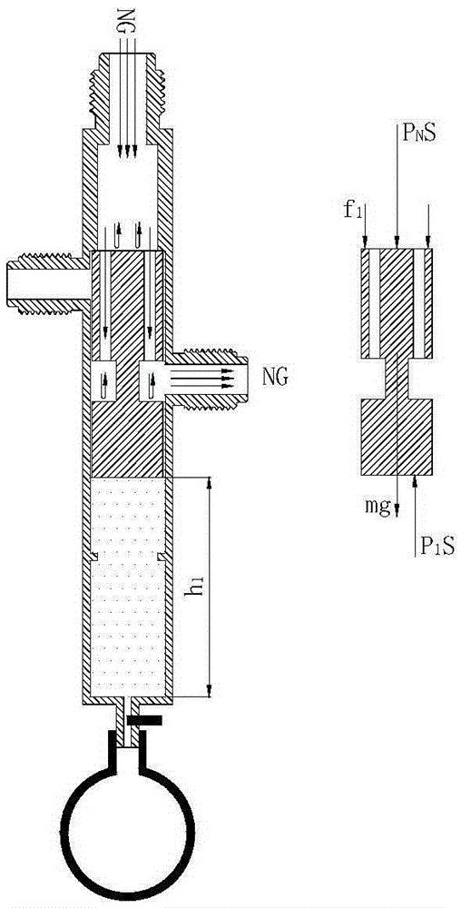
[0033] Please refer to figure 1 , Embodiment 1 of the present invention is: a column-type gas identification device, including a column-type housing 1, the upper end of the column-type housing 1 is a gas inlet 2, and the two sides are respectively provided with a low-pressure gas outlet 31 and a high-pressure gas outlet 32, wherein the position of the high-pressure gas outlet 32 is higher than that of the low-pressure gas outlet 31. Below the cavity inside the housing is a sealed cavity 4, and the sealed cavity 4 is filled with inert gas. Above the sealing chamber 4 is the first sealing piston 5. The first sealing piston 5 is also columnar, which just fits the inner wall of the housing cavity and can move up and down along the inner wall of the cavity to ensure airtightness and at the same time the friction force is very small , can be ignored. A groove 6 is provided on the side of the first sealing piston, and a gas passage 7 is provided from the upper end of the first se...
Embodiment 2
[0071] Please refer to Figure 5 The difference between the second embodiment of the present invention and the first embodiment is that a spring is used instead of an inert gas. Such as Figure 5 As shown, a spring 12 is provided in the sealing chamber 4. In order to ensure the normal deformation of the spring, it is preferable that one end of the spring 12 is connected to the first sealing piston. Of course, as long as the spring size is suitable and can deform normally, it may not be connected to the first sealing piston. , but only deformed by the piston pressure. Further, in order to ensure that the spring deforms in the vertical direction, a spring guide shaft 13 with one end connected to the first sealing piston can also be provided in the sealing chamber 4, and the spring 12 is arranged around the spring guide shaft. The other end of the spring guide shaft passes through the housing from the bottom of the sealing cavity. When the first sealing piston is compressed and...
Embodiment 3
[0082] Please refer to Figure 8 The difference between the third embodiment of the present invention and the first and second embodiments is that the deformation mode of the inert gas and the spring is changed to a hydraulic structure. In this embodiment, the casing 1 is a U-shaped column structure, one end of the U-shaped column is the gas inlet 2, the other end is the gas outlet 16, and the liquid sealing chamber 14 is located below the first sealing piston 5, and the liquid The sealing chamber 14 is also U-shaped, one end of which is connected to the first sealing piston 5 , and the other end is connected to the second sealing piston 15 . Affected by the gas pressure above the first sealing piston 5 , the first sealing piston 5 can be pushed down, thereby pushing the liquid in the liquid sealing chamber 14 and the second sealing piston 15 to move accordingly. For the rationality of the gas outlet, the high-pressure gas outlet and the low-pressure gas outlet can be arrange...
PUM
 Abstract
Description
Claims
Application Information
 - R&D
- Intellectual Property
- Life Sciences
- Materials
- Tech Scout
- Unparalleled Data Quality
- Higher Quality Content
- 60% Fewer Hallucinations
Browse by: Latest US Patents, China's latest patents, Technical Efficacy Thesaurus, Application Domain, Technology Topic, Popular Technical Reports.
© 2025 PatSnap. All rights reserved.Legal|Privacy policy|Modern Slavery Act Transparency Statement|Sitemap|About US| Contact US: help@patsnap.com