Dynamometer with self-check function

A dynamometer and functional technology, applied in the field of dynamometers, can solve the problems that the dynamometer cannot be fixed, the detection test cannot be carried out, etc., and achieve the effects of easy observation and reading, simple structure and convenient operation.

Active Publication Date: 2016-03-02
HARBIN TURBINE +1
View PDF6 Cites 0 Cited by
  • Summary
  • Abstract
  • Description
  • Claims
  • Application Information

AI Technical Summary

Problems solved by technology

[0003] In order to solve the problem that the existing dynamometer cannot be fixed during detection, resulting in the inability to carry out the detection test, the invention further proposes a dynamometer with self-test function

Method used


Image

  • Dynamometer with self-check function

Examples


specific Embodiment approach 1

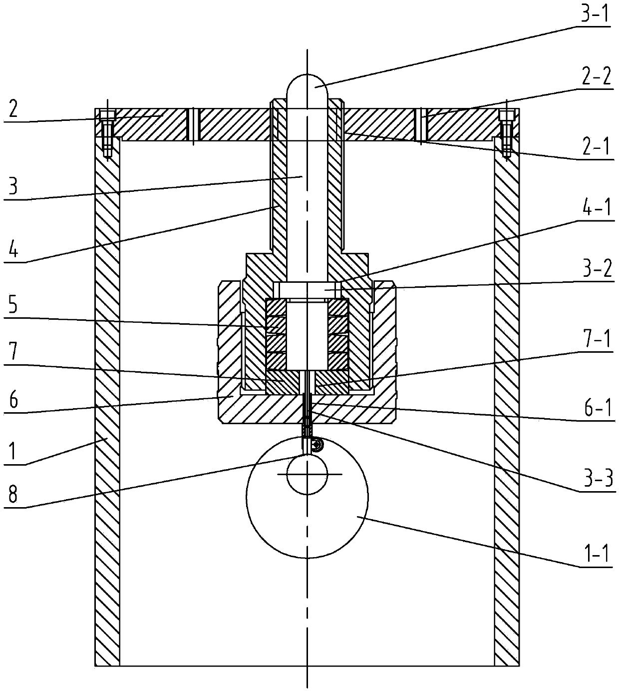
[0008] Specific implementation mode one: combine figure 1 Explain that a dynamometer with self-test function described in this embodiment includes an outer shell 1, an upper cover plate 2, a push rod 3, a sleeve 4, a spring leaf 5, a fixing seat 6, a bottom plate 7 and a dial indicator 8 , the outer casing 1 is a cylindrical body with openings at both ends, the upper end surface of the outer casing 1 is fixedly connected with an upper cover plate 2, the middle part of the upper cover plate 2 is provided with a first threaded through hole 2-1, and the sleeve 4 is arranged on In the outer shell 1, the upper end of the sleeve 4 is screwed into the first threaded through hole 2-1, the inside of the sleeve 4 is inserted with a push rod 3, and the inside of the lower end of the sleeve 4 is provided with a positioning groove 4-1, and the top The middle part of the rod 3 is provided with a boss 3-2, and the boss 3-2 is arranged at the bottom of the positioning groove 4-1, the outer si...

specific Embodiment approach 2

[0010] Specific implementation mode two: combination figure 1 Explain that the side wall of the upper end of the ejector rod 3 and the inner side wall of the upper end of the sleeve 4 in this embodiment are slidably connected in the vertical direction, and the side wall of the tail rod 3-3 is connected with the hole wall of the through hole 6-1 of the fixing seat in the vertical direction. Swipe to connect. Other compositions and connection methods are the same as those in Embodiment 1.

[0011] Such a design can ensure that the ejector rod 3 moves up and down in the vertical direction, and prevent the ejector rod 3 from tilting, thereby affecting the measurement effect.

specific Embodiment approach 3

[0012] Specific implementation mode three: combination figure 1 To illustrate, the lower end of the sleeve 4 in this embodiment is fixedly connected to the fixing seat 6 . Other compositions and connection modes are the same as those in Embodiment 1 or 2.


PUM

PropertyMeasurementUnit
diameteraaaaaaaaaa
thicknessaaaaaaaaaa
thicknessaaaaaaaaaa

Abstract

The invention discloses a dynamometer with a self-check function, relates to a dynamometer and especially relates to a dynamometer with a self-check function, for solving the problem of incapability of a detection test, caused by incapability of fixing a conventional dynamometer during detection. The dynamometer with the self-check function comprises an outer casing, an upper cover plate, a push rod, a sleeve, a spring sheet, a fixation seat, a base plate and a dial gauge, wherein the outer casing is a cylinder with openings at two ends, the upper end surface of the outer casing is fixedly connected with the upper cover plate, the central portion of the upper cover plate is provided with a first threaded through hole, the sleeve is arranged in the outer casing, the upper end of the sleeve is screwed into the first threaded through hole, the push rod is inserted into the sleeve, the central portion of the push rod is provided with a boss, the lower end of the push rod is provided with a tail rod, the spring sheet sleeves the push rod, the lower end of the fixation seat is provided with the dial gauge, a center of the push rod abuts against the tail end of the tail rod, and the side wall of the outer casing is provided with an observation hole. The dynamometer provided by the invention is applied to measurement of size of a force.

Description

technical field [0001] The invention relates to a dynamometer, in particular to a dynamometer with a self-checking function. Background technique [0002] When the dynamometer used in the steam turbine unit is tested, it is usually necessary to apply a large load of 10 tons to 35 tons on the top, and use a dial gauge to measure the deformation of the spring leaf during the process and return at the lower end. The meter cannot be fixed during the detection process, resulting in the failure of the detection test. Contents of the invention [0003] In order to solve the problem that the existing dynamometer cannot be fixed during detection, resulting in the failure of the detection test, the invention further proposes a dynamometer with a self-test function. [0004] The technical scheme adopted by the present invention to solve the above-mentioned technical problems is: the present invention includes an outer shell, an upper cover plate, a push rod, a sleeve, a spring leaf,...

Claims


Application Information

Patent Timeline
Patent Type & Authority Applications(China)
IPC IPC(8): G01L1/00G01L25/00
Inventor 王天巍刘中伟李静刘新新李宇峰
Owner HARBIN TURBINE
Why Eureka
Try Eureka